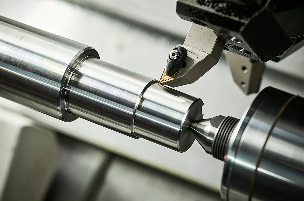
Steam turbine rotor precision machining affects turbine efficiency, vibration, bearing stability, and service life. A rotor operates at high speed and under heavy thermal and mechanical loads. For this reason, manufacturers must control the machining datum, coaxiality, runout, surface integrity, material condition, and dynamic balance.
This guide explains the main machining steps, accuracy requirements, inspection methods, and supplier-selection criteria.
What Is a Steam Turbine Rotor?
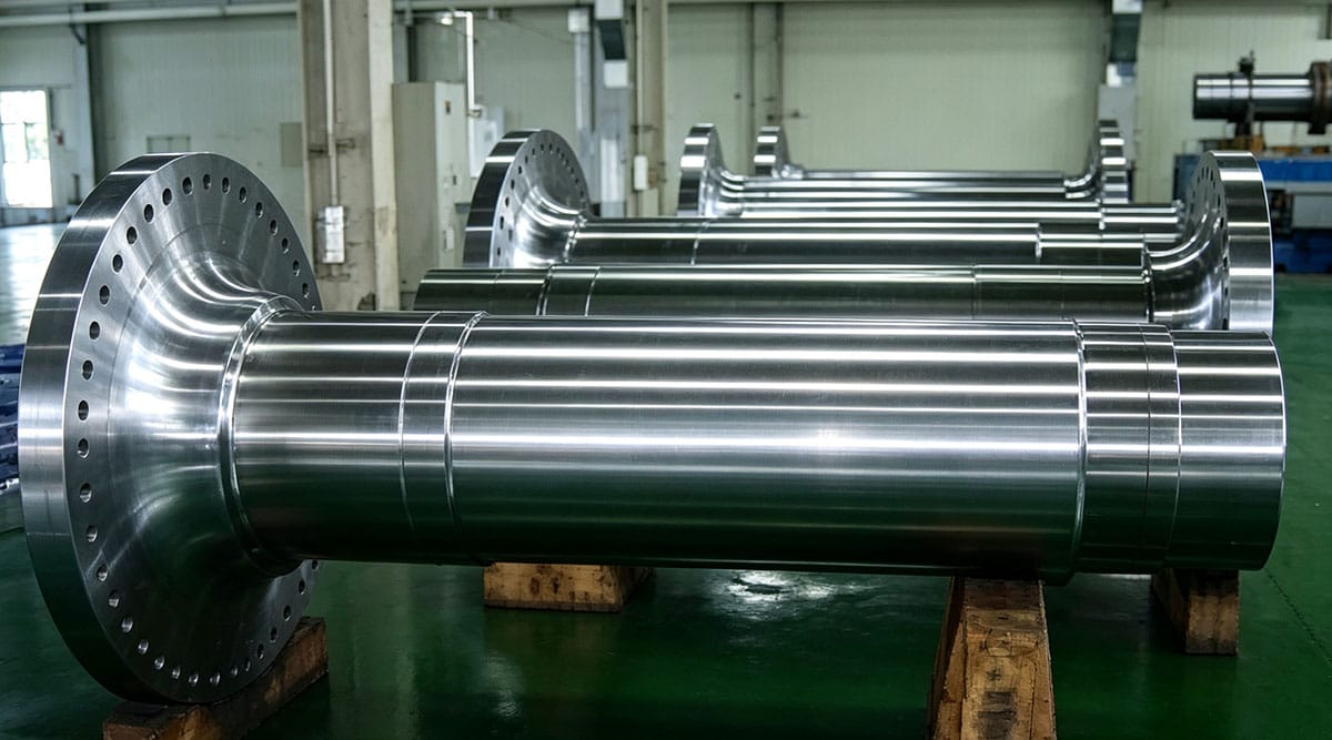
A steam turbine rotor is the rotating shaft assembly that converts steam energy into mechanical power. It may include journals, wheel or disk sections, coupling flanges, sealing areas, and center holes.
Most rotors start as large forged alloy-steel components. Before final machining, the forging usually receives heat treatment and non-destructive testing. These steps help verify material properties and identify internal or surface defects.
Why Precision Machining Matters
The rotor must remain stable and accurately aligned during high-speed operation. If coaxiality, concentricity, roundness, or radial runout is incorrect, vibration and bearing loads can increase. In addition, surface defects can reduce fatigue strength and service life.
- Excessive vibration and rotor instability
- Uneven bearing loading
- Seal leakage
- Premature wear
- Lower turbine reliability and efficiency
Steam Turbine Rotor Machining Process
1. Review the Forging and Material
First, the manufacturer reviews the drawing, material specification, heat-treatment requirements, machining allowance, and inspection plan. Ultrasonic testing can detect internal discontinuities in large forgings. Magnetic particle inspection can also identify surface or near-surface cracks in suitable materials.
2. Perform Rough Turning
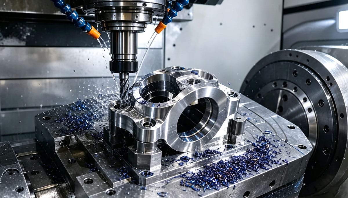
Heavy-duty CNC turning removes excess forging material and establishes the basic rotor geometry. The machine must have enough rigidity, spindle capacity, workholding stability, and alignment accuracy. Proper cutting parameters also help control heat, cutting forces, and deformation.
3. Machine the Center Holes
Center holes and other reference features may be machined at an early stage. These features support later turning, grinding, and inspection. Their position and condition are important because errors in the primary datum can affect every later operation.
4. Control Heat Treatment and Stress Relief
The rotor may require quenching and tempering, stress relieving, or another approved heat-treatment process. Large forgings can bend or change size during treatment. Therefore, the process may include straightening, reference restoration, and intermediate measurement.
5. Complete Semi-Finish Turning
Semi-finish turning brings journals, wheel sections, flanges, sealing areas, and other functional surfaces close to their final dimensions. At this stage, the manufacturer checks the rotor axis, machining references, stock allowance, and distortion condition.
6. Finish Turning and Grinding
Precision turning finishes features that require close dimensional and geometric control. Cylindrical grinding may finish journals and other surfaces that need tighter tolerances or a better surface finish.
Grinding quality depends on wheel selection, feed rate, grinding speed, coolant delivery, dressing frequency, and temperature control. Poor settings can cause grinding burns, cracks, residual stress, and other surface defects.
7. Complete Dynamic Balancing
After machining, the rotor undergoes dynamic balancing. The balancing machine measures the amount and position of imbalance. The manufacturer then removes material, or uses another approved correction method, to reduce vibration during operation.
Critical Accuracy Requirements
Actual tolerances depend on the rotor design, operating speed, material, bearing system, customer drawing, and applicable standards. Generic values should not replace drawing requirements. Common control points include:
- Journal diameter and cylindricity
- Roundness and surface roughness
- Coaxiality and concentricity
- Radial and axial runout
- Wheel-section and sealing-feature locations
- Center-hole position and condition
- Dynamic balance and correction records
Inspection and Quality Assurance
A complete quality plan combines material verification, in-process measurement, final inspection, non-destructive testing, balancing, and document traceability.
Dimensional and Geometric Inspection
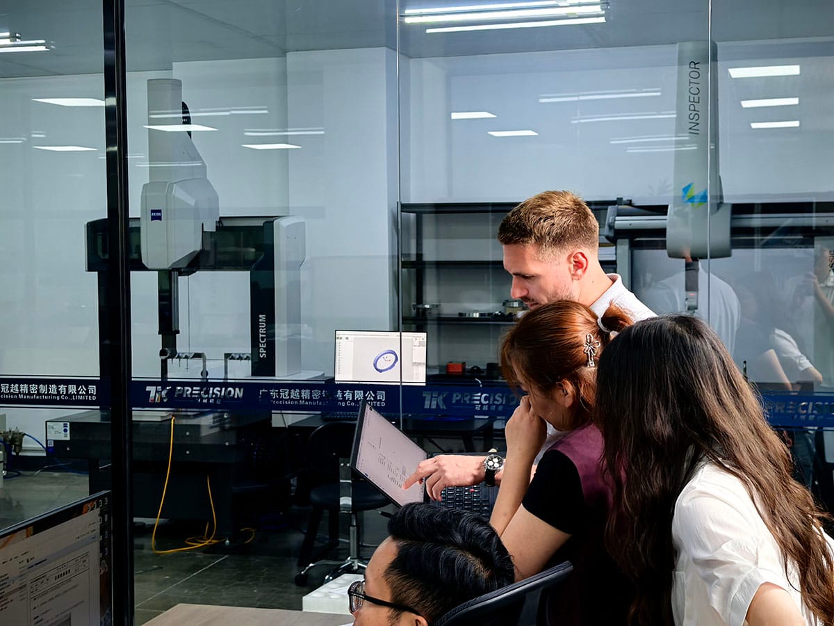
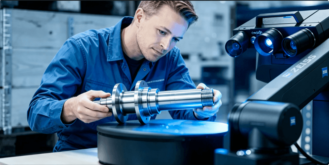
Precision instruments, roundness equipment, rotor measurement systems, and coordinate measuring machines can verify diameter, roundness, cylindricity, coaxiality, runout, feature location, and surface roughness.
Non-Destructive Testing
Ultrasonic testing checks for internal discontinuities in large forgings. Magnetic particle inspection checks for surface and near-surface indications on suitable ferromagnetic materials. The approved specification should define the method and acceptance criteria.
Balance and Documentation
Balance results should be recorded with material certificates, heat-treatment records, inspection reports, testing results, calibration information, and final release documents. This record provides traceability and supports future maintenance.
How to Choose a Rotor Machining Partner
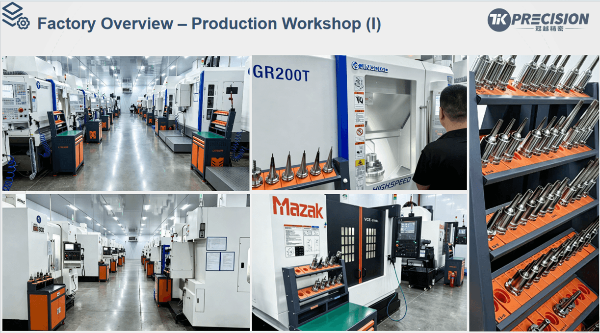
Do not evaluate a supplier by its machine list alone. A qualified partner should show experience with large forgings, heavy-duty CNC turning, precision grinding, heat-treatment coordination, rotor measurement, dynamic balancing, and quality documentation.
- Check the maximum workpiece size, weight, diameter, and length.
- Confirm experience with alloy-steel forgings and critical rotating parts.
- Ask how the supplier controls datums, deformation, runout, and surface integrity.
- Verify inspection, calibration, non-destructive testing, and balance capabilities.
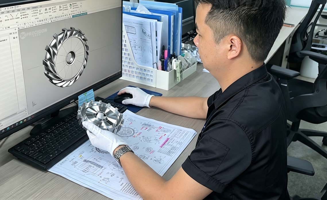
- Provide the drawing, 3D model, material, quantity, and delivery requirements for review.
Conclusion
Reliable steam turbine rotor manufacturing requires a controlled sequence. The sequence includes forging inspection, rough machining, reference preparation, heat-treatment management, precision turning, grinding, dimensional inspection, non-destructive testing, and dynamic balancing.
The best results come from using a consistent datum, limiting heat-treatment distortion, controlling coaxiality and runout, protecting surface integrity, and recording every critical inspection result. Provide the rotor drawing or 3D model for a technical review and quotation.
Frequently Asked Questions
What material is commonly used for steam turbine rotors?
Large steam turbine rotors commonly use high-strength forged alloy steel. The exact grade and heat-treatment condition depend on the turbine design and operating requirements.
Why is dynamic balancing necessary?
Even a small mass imbalance can create a large centrifugal force at high speed. Dynamic balancing reduces imbalance and helps limit operating vibration.
What information is needed for a quotation?
Useful information includes the drawing or 3D model, material, finished dimensions, tolerances, quantity, surface finish, inspection requirements, and delivery schedule.