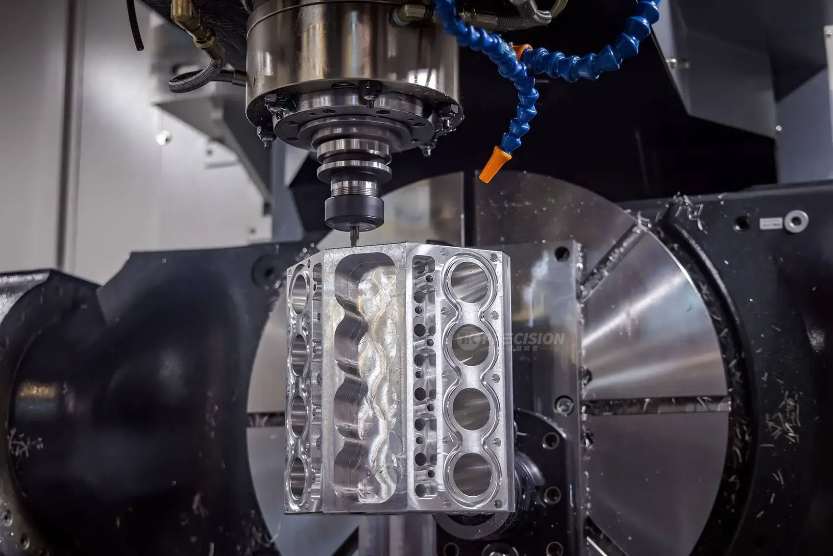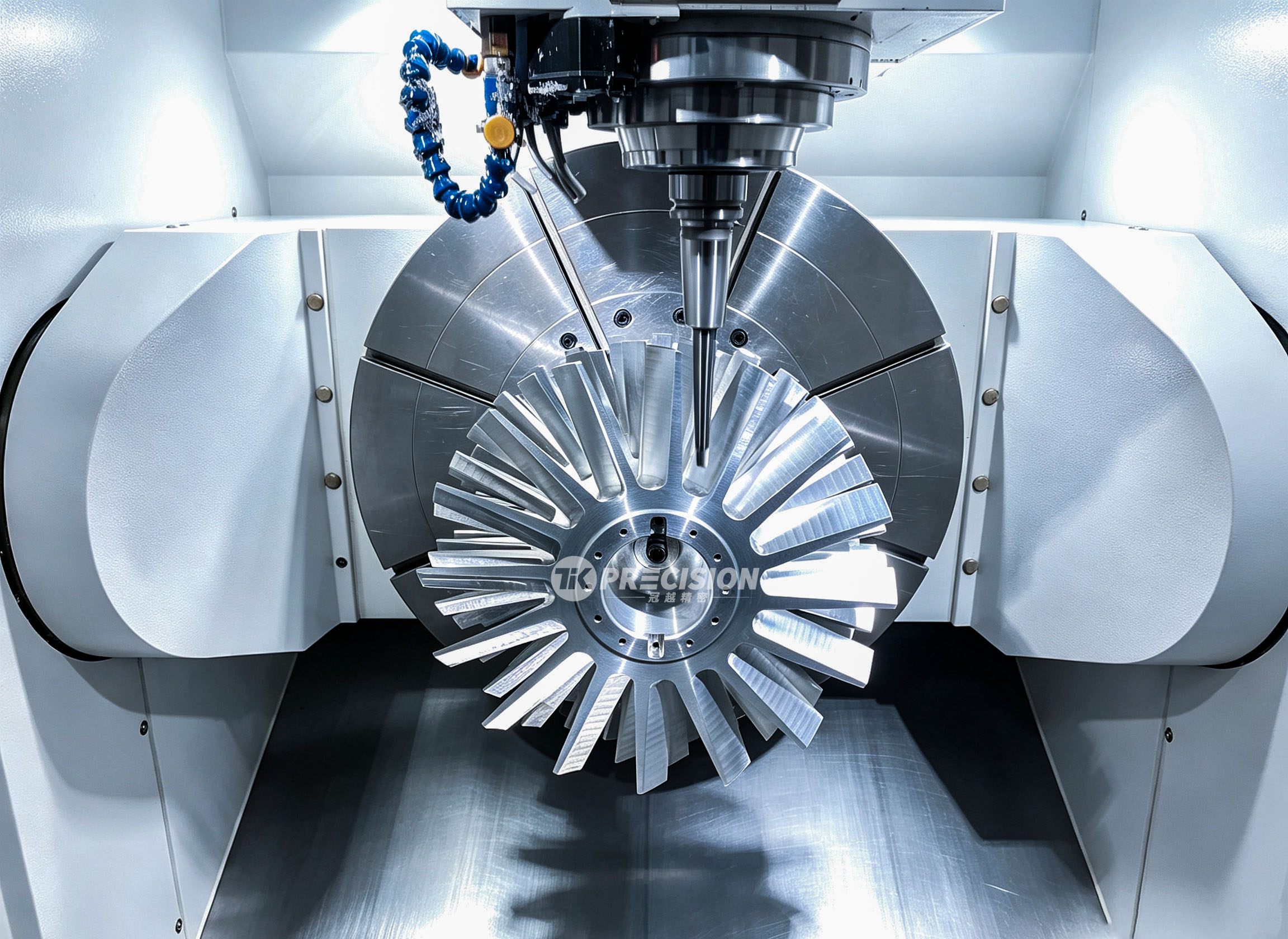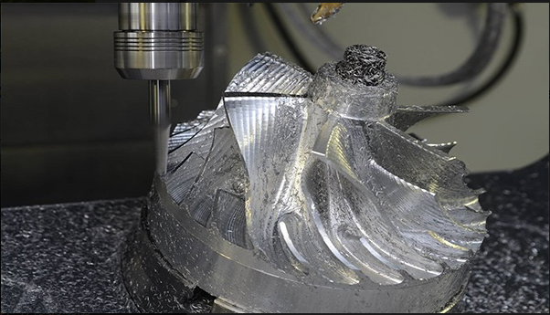
The fan blades are the heart of any ducted fan system. They are the components that do the aerodynamic work — accelerating air, generating thrust, and operating under complex combinations of centrifugal, aerodynamic, and vibratory loads. Machining these blades from solid metal requires an intimate understanding of airfoil geometry, 5-axis toolpath strategies, thin-wall machining dynamics, and the surface finish requirements that govern aerodynamic performance. This article provides a detailed guide to the CNC machining of ducted fan blade airfoils.
Blade Geometry: From Airfoil Section to 3D Surface
A ducted fan blade is defined by stacking two-dimensional airfoil sections along a radial (spanwise) axis. Each section is characterized by its chord length, camber, thickness distribution, and stagger angle (the angle between the chord line and the plane of rotation). These parameters vary from root to tip, creating a three-dimensional twisted and tapered surface.
Typical Airfoil Families for Ducted Fans
- NACA 4-digit series (e.g., NACA 4412, NACA 6412): Simple, well-documented, and tolerant of manufacturing variations. Commonly used in industrial ducted fans and lower-speed UAV fans where maximum efficiency is not critical.
- NACA 65-series: Designed for low drag at high subsonic Mach numbers. The 65-series has a favorable pressure gradient over a large portion of the chord, delaying transition to turbulent flow. Used in higher-speed ducted fan applications.
- Custom / inverse-designed airfoils: For high-performance ducted fans (UAV propulsion, racing drone ducts), airfoil profiles are custom-designed using CFD optimization. These profiles may have non-standard thickness distributions, reflex camber for stability, or specialized leading edge shapes for particular Reynolds number ranges.
Blade Geometric Parameters and Their Manufacturing Implications
| Parameter | Typical Range | Manufacturing Challenge |
|---|---|---|
| Blade thickness (root) | 3-8 mm | Provides structural stiffness for machining |
| Blade thickness (tip) | 0.5-2.0 mm | Thin sections prone to deflection, chatter, and vibration during machining |
| Blade chord length | 20-100 mm (varies with fan diameter) | Short chords limit tool access between blades |
| Blade span | 20-200 mm | Long spans require long-reach tools with high L/D ratios |
| Blade count | 5-15 blades | Higher blade counts reduce inter-blade space, making tool access more difficult |
| Leading edge radius | 0.1-0.5 mm | Very small radii are difficult to machine accurately; require small tools and fine stepovers |
| Trailing edge thickness | 0.1-0.3 mm | Extremely thin; susceptible to burr formation and breakage during machining |
5-Axis Toolpath Strategies for Blade Machining
Roughing: Efficient Bulk Material Removal
- Adaptive clearing (trochoidal milling): The primary roughing strategy for inter-blade material removal. A constant tool engagement angle (typically 10-15% of the tool diameter) is maintained throughout the toolpath, preventing the tool from ever being fully buried in a narrow slot. Trochoidal paths also promote chip evacuation from deep blade channels.
- Plunge roughing: An alternative for very deep, narrow blade channels where trochoidal paths may not be feasible due to tool length constraints. The tool plunges axially into the material, cutting with its end rather than its side. Plunge roughing imposes primarily axial loads on the tool, reducing the lateral deflection that plagues long-reach side milling.
- Tool selection: Roughing end mills with corner radii (not sharp corners) for longer tool life. Diameters of 4-8 mm depending on blade spacing. Variable-helix or variable-pitch designs to suppress chatter in thin-wall sections.
Semi-Finishing: Establishing the Blade Shape
- Flank milling (swarf cutting): Wherever the blade surface is developable (i.e., can be generated by a straight line moving along the surface), flank milling with the side of a tapered end mill or barrel cutter removes material much faster than point milling. Ducted fan blade surfaces are often nearly developable — the slightly twisted nature of the blade means they are not perfectly developable, but the error is small enough that flank milling can be used for semi-finishing with 0.1-0.2 mm of stock left for the finish pass.
- Z-level semi-finishing: For blade sections near the tip where flank milling would be inaccurate due to twist, Z-level (waterline) semi-finishing with a ball end mill traces the blade profile at discrete Z heights. Step-down values of 0.5-1.0 mm are typical.
Finishing: Achieving Aerodynamic Surface Quality
- Spiral / flowline finishing with ball end mill: The tool traces a continuous spiral path from the blade leading edge to the trailing edge, or from the hub to the tip. Flowline toolpaths cut along the natural direction of the surface, producing a consistent surface texture that aligns with the airflow direction — beneficial for aerodynamic performance. Stepover values of 0.03-0.08 mm produce surface finishes of Ra 0.4-0.8 µm.
- Leading and trailing edge finishing: The blade leading edge (LE) and trailing edge (TE) are the most critical regions for aerodynamic performance. A separate finishing toolpath with smaller stepover (0.02-0.05 mm) and a dedicated edge tool (sharp-corner ball end mill or small-radius end mill) ensures these thin, high-curvature features are accurately machined.
- Tool axis orientation: The tool axis should be tilted 10-20° from the surface normal to avoid cutting with the center of the ball end mill, where the cutting speed is zero and chip formation is poor. The tilt direction should be such that the tool is leaning away from adjacent blades to avoid collision.
Managing Thin-Wall Machining Challenges
- Blade deflection during machining: The thin tip sections of ducted fan blades act as cantilever beams. Under cutting forces, the blade tip can deflect by 0.05-0.15 mm, causing dimensional errors and poor surface finish. Mitigation strategies include:
- Leaving a thick “web” of material connecting adjacent blade tips during roughing and semi-finishing — this web is removed only during the final finish passes, when cutting forces are lightest.
- Using very light depths of cut (0.02-0.05 mm radial engagement) for finishing passes.
- High spindle speeds (20,000-40,000 RPM) to reduce cutting forces.
- Sharp cutting tools — a sharp cutting edge (edge radius < 5 µm) reduces ploughing forces that dominate when the chip thickness is small relative to the edge radius.
- Chatter suppression: Thin blades have natural frequencies that can be excited by the tooth-passing frequency of the cutting tool. Spindle speed selection should avoid blade natural frequencies and their harmonics. Stability lobe diagrams, generated by tap-testing the blade or from FEM modal analysis, guide speed selection. Variable-pitch end mills disrupt the regular tooth-passing frequency that drives regenerative chatter.
- Residual stress distortion: Removing 70-90% of the billet material releases residual stresses in the remaining thin blade structure. The blades may spring several hundredths of a millimeter when the final material is removed. Stress-relief heat treatment (T7 for aluminum alloys) after rough machining is standard practice for precision blades.
Surface Finish Requirements
- Blade pressure and suction surfaces: Ra 0.4-0.8 µm. Smoother surfaces reduce skin friction drag and delay the laminar-to-turbulent boundary layer transition, improving fan efficiency. For high-performance UAV fans, Ra 0.2-0.4 µm may be specified — achieved by reduced stepover values or by post-machining polishing (manual, abrasive flow, or electropolishing).
- Surface texture direction: Machining marks should ideally be aligned with the airflow direction (streamwise) rather than perpendicular to it. Flowline toolpaths that trace along the blade span or chord direction achieve this.
- Leading edge surface finish: The leading edge is the most sensitive region to surface finish and profile accuracy. A small radius of curvature amplifies the effect of any surface irregularity. Manual polishing with progressively finer abrasive media is common for leading edges, though automated robotic polishing is increasingly used for production.
Inspection of Machined Blades
- CMM airfoil inspection: A CMM with a small probe measures the blade at multiple spanwise sections (root, 25%, 50%, 75%, tip). At each section, 30-50 points are measured around the airfoil perimeter. The measured data is compared to the nominal airfoil section, and deviations in profile, thickness, camber, and stagger angle are reported.
- Blade-to-blade variation: All blades on the rotor should be measured, and the variation between blades quantified. Blade-to-blade aerodynamic differences create unsteady forces at the blade-passing frequency — a source of vibration and noise.
- Optical / laser scanning: Structured-light 3D scanners capture the entire blade surface in a point cloud, enabling a full-field comparison to the CAD model. This is increasingly the preferred method for first-article inspection and process development, as it provides far more data density than touch-probe CMM.
Tik Precision machines ducted fan rotors on our 5-axis CNC platforms, with CAM programming optimized for thin-wall airfoil machining. We understand the interplay between cutting strategy, surface finish, and aerodynamic performance. Contact us for a quote on your ducted fan blade requirements.