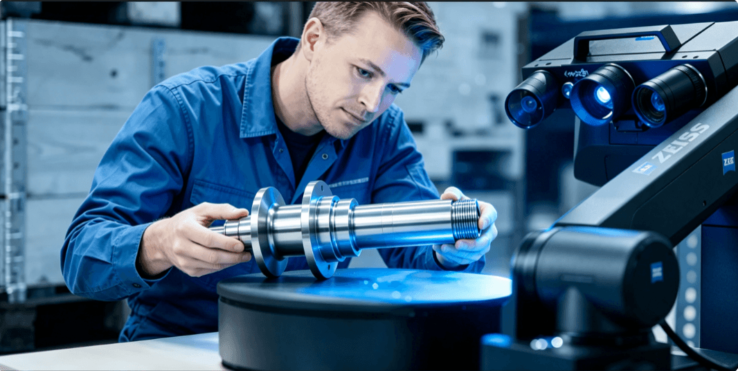
CNC machined parts can look perfect and still fail inspection. A single incorrect dimension, datum error, surface defect, or geometric tolerance can make a part unacceptable.
For engineers, manufacturers, and purchasing teams, understanding these inspection failures helps prevent rework, delays, and quality claims. This guide explains 10 common causes and practical ways to reduce the risk.
1. Incorrect Drawing Interpretation
Engineering drawings include more than basic dimensions. They also define datums, geometric tolerances, surface finish, materials, threads, and critical features.
If the manufacturing team misunderstands one requirement, the error can affect every later operation. A pre-production drawing review helps confirm the design intent before machining begins.
2. Poor Datum Definition
Datums determine how a part is positioned, machined, and inspected. If the machining and inspection teams use different datum references, the part may pass one check but fail another.
To avoid this problem, confirm the datum structure, inspection setup, and measurement references before production.
3. Excessive Tool Wear
Cutting tools wear over time. As the cutting edge changes, dimensions, surface finish, burrs, and edge quality can also change.
Tool-life monitoring, scheduled tool replacement, and first-piece checks help maintain consistent results, especially in high-volume production.
4. Thermal Expansion
Temperature affects both the machine and the workpiece. Heat from the spindle, cutting process, coolant, or surrounding environment can change dimensions during machining and inspection.
Stable environmental conditions, warm-up routines, temperature monitoring, and controlled inspection timing are important for high-precision components.
5. Incorrect Workholding
Improper fixturing can cause part movement, deformation, positioning errors, and vibration. Thin-wall parts are especially sensitive to clamping force.
A suitable fixture should support the part without over-constraining it. The setup should also provide repeatable location and safe access for cutting tools and inspection equipment.
6. Inadequate Inspection Methods
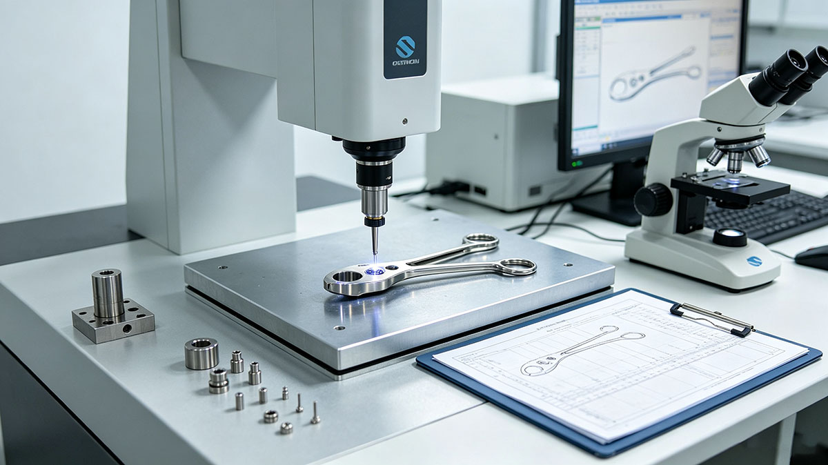
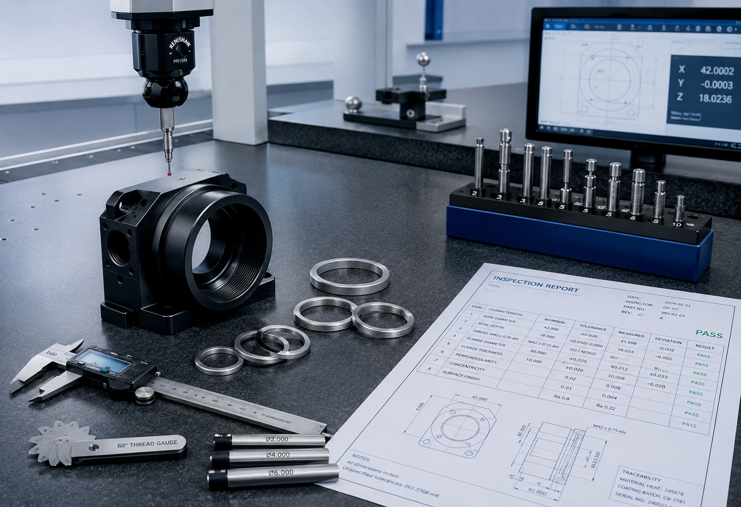
Calipers and micrometers are useful for basic dimensions, but they cannot verify every feature. Complex geometries may require a coordinate measuring machine, optical measurement, surface measurement, or specialized gauges.
The inspection method must match the feature, tolerance, functional requirement, and approved measurement procedure.
7. Material Variation
Material condition influences cutting behavior and dimensional stability. Hardness, heat-treatment condition, residual stress, and material batch can affect tool wear, deformation, and surface quality.
Incoming material inspection and review of material certificates help identify potential risks before machining starts.
8. Incorrect Machining Sequence
The order of operations affects the final result. For example, machining thin sections too early can cause deformation during later operations.
An effective process plan considers part geometry, residual stress, material removal, clamping, heat generation, and inspection access. Roughing, stress relief, semi-finishing, and finishing should be sequenced carefully.
9. Dimensional Changes After Surface Treatment
Anodizing, plating, coating, heat treatment, and other secondary processes can change dimensions or surface condition.
Critical features should be reviewed before and after treatment. The drawing should clearly identify which dimensions apply before treatment and which apply to the finished part.
10. Lack of Process Control
Final inspection finds problems, but it does not prevent them. A stronger quality strategy monitors the process from material receipt to final release.
- Incoming material inspection
- First-piece inspection
- In-process measurement
- Tool monitoring
- Final dimensional inspection
- Documented nonconformance and corrective action
These controls help identify problems before an entire production batch is affected.
How to Prevent CNC Inspection Failures
Use a preventive approach rather than relying only on final inspection:
- Review the drawing and confirm all critical requirements.
- Align manufacturing and inspection datums.
- Evaluate material condition and machining risks.
- Choose suitable tooling, fixtures, and machining parameters.
- Measure the first part before continuing production.
- Monitor tool wear, temperature, and process stability.
- Use the correct inspection equipment for each feature.
- Record results and investigate trends before they become defects.
Conclusion
CNC machining inspection failures rarely come from one factor. They often result from a combination of drawing interpretation, datums, machine capability, tooling, material behavior, fixturing, machining sequence, surface treatment, and inspection methods.
Quality should be built into the manufacturing process, not checked only after production is complete. Clear requirements, controlled processes, and appropriate measurement methods can reduce rework and improve delivery reliability.
Frequently Asked Questions
Why do CNC parts fail inspection?
Common causes include incorrect drawing interpretation, datum errors, tool wear, thermal expansion, poor fixturing, material variation, incorrect machining sequence, surface-treatment changes, and inadequate inspection.
How can manufacturers reduce inspection failures?
Manufacturers can reduce failures through drawing review, first-piece inspection, in-process measurement, tool monitoring, stable machining conditions, suitable fixtures, and a documented quality-control plan.
What information helps diagnose a failed CNC part?
Useful information includes the drawing, inspection report, failed dimensions, material and heat-treatment records, machining process, fixture details, surface-treatment requirements, and measurement method.
Need Help With CNC Machining Quality?
Share your drawing, CAD model, inspection report, material requirements, and quality concerns for a technical review. An early DFM and process review can help identify manufacturing risks before production begins.