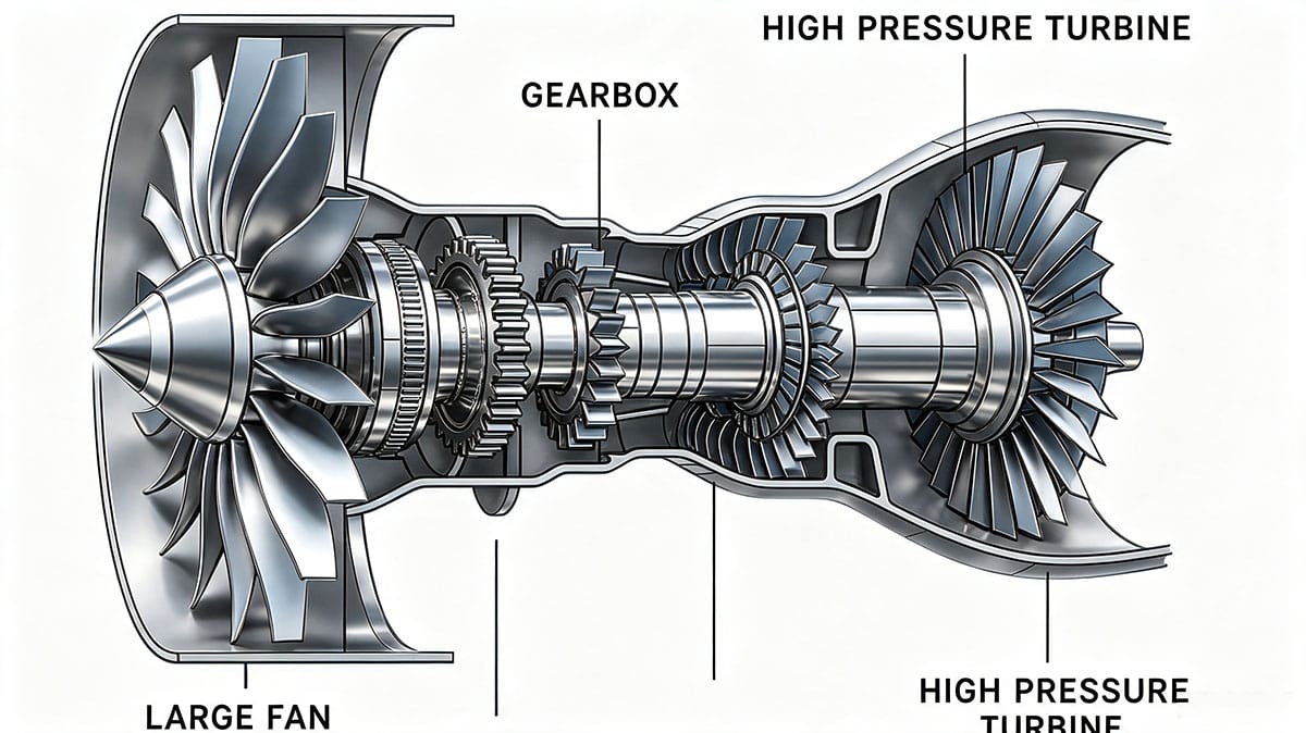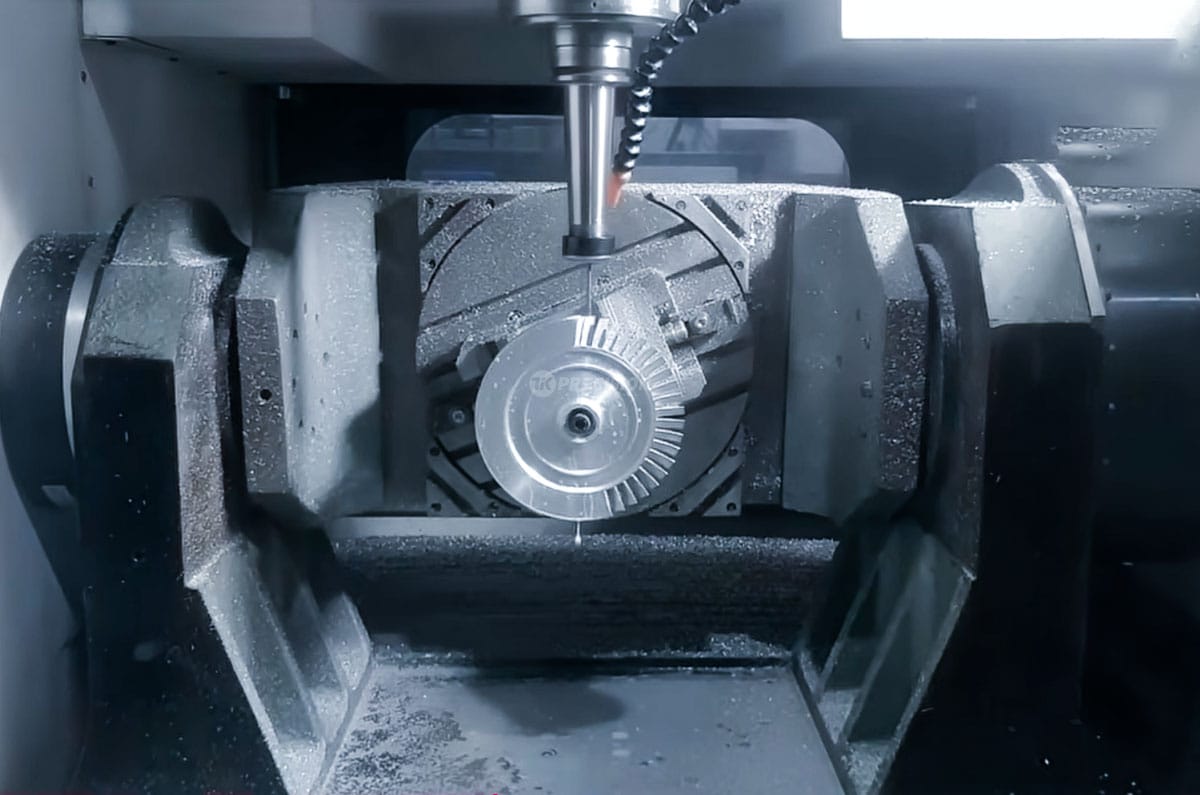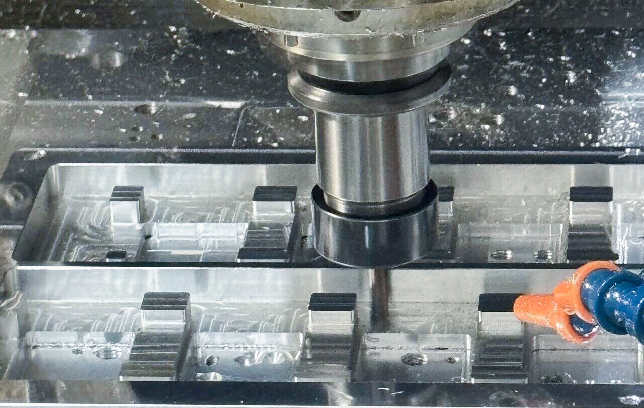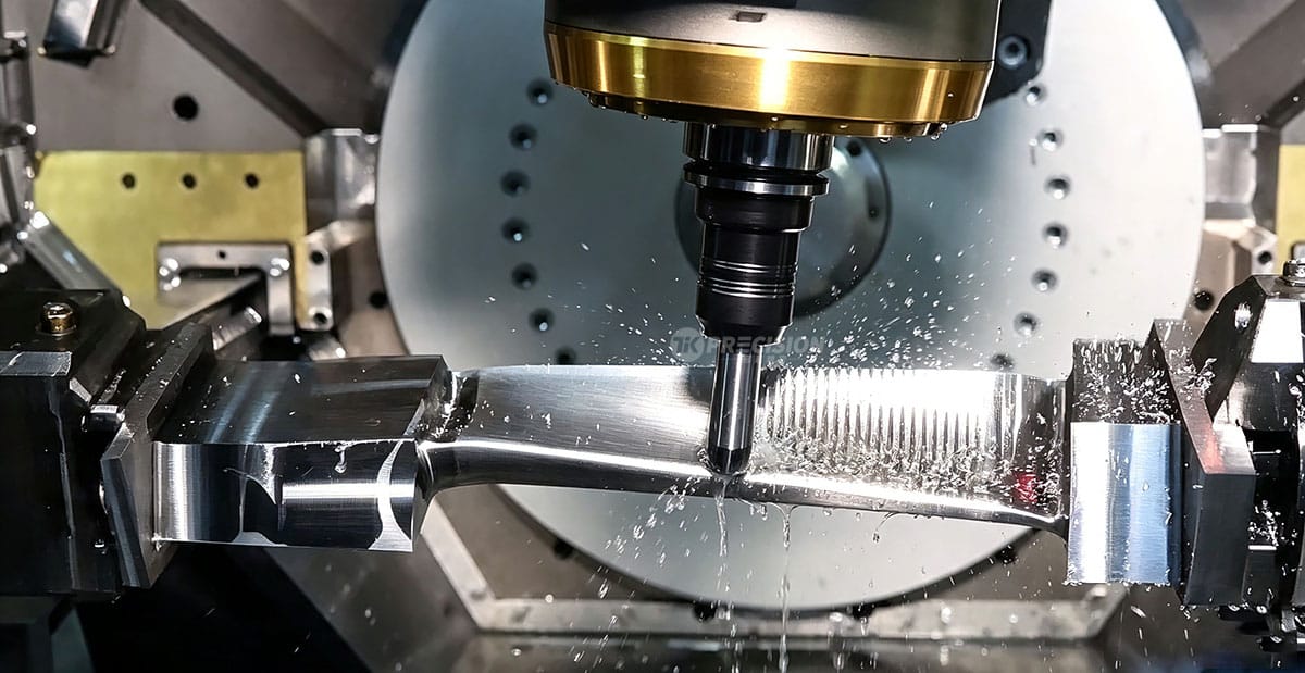
Thin-wall geometry is a defining characteristic of many aerospace turbine components, from blade airfoils to large-diameter casings. While thin walls help reduce engine weight and improve aerodynamic efficiency, they also make parts highly susceptible to distortion during CNC machining. Controlling this distortion is one of the most persistent technical challenges in aerospace manufacturing.
Root Causes of Distortion
- Clamping-induced deformation: Thin-wall sections have low inherent stiffness, so uneven or excessive clamping force can elastically deform the part during machining, with springback occurring once the part is unclamped.
- Cutting force deflection: High cutting forces, particularly when machining superalloys or titanium, can cause thin sections to deflect momentarily during cutting, leading to dimensional inconsistency.
- Residual stress redistribution: Forged and cast aerospace materials contain internal residual stress from their original forming process. As material is progressively removed, this stress redistributes and can cause the part to move or warp.
- Thermal effects: Heat generated during cutting, combined with machine tool thermal drift over long cycle times, can introduce additional dimensional variation.
Process-Level Distortion Control Strategies
Process Planning
- Separating roughing and finishing operations, with stress-relief heat treatment scheduled in between to stabilize the part.
- Balanced, symmetric material removal sequences where feasible, reducing the likelihood of one-sided stress release causing directional warping.
- Sequencing rigid features before flexible ones, machining higher-stiffness reference features first.
Fixturing Strategy
- Flexible, multi-point adjustable tooling in place of rigid clamps, distributing holding force more evenly.
- Sacrificial process bosses and stiffening features, designed into the part early to temporarily increase local rigidity.
- Vacuum fixturing and low-stress workholding, used to minimize clamping-induced deformation.
Cutting Parameter Optimization
- Reduced depth of cut and moderate feed rates in distortion-sensitive zones to lower peak cutting forces.
- Tool geometry selection aimed at minimizing radial cutting force components.
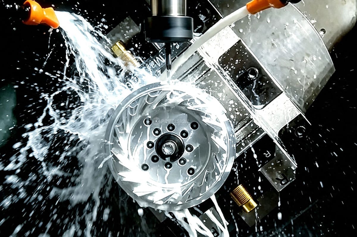
- Enhanced coolant delivery to reduce localized thermal expansion.
In-Process Measurement and Compensation
For features where distortion cannot be fully eliminated through process design alone, many manufacturers implement an intermediate measurement step. The measured deviation data is then used to apply compensation to the finishing toolpath, a standard practice for high-precision aerospace turbine blades and components.
Conclusion
Distortion control in thin-wall aerospace turbine parts requires a coordinated approach spanning process planning, fixture design, and precision tolerances control. Manufacturers with deep process experience are consistently able to deliver the dimensional stability that aerospace programs require.