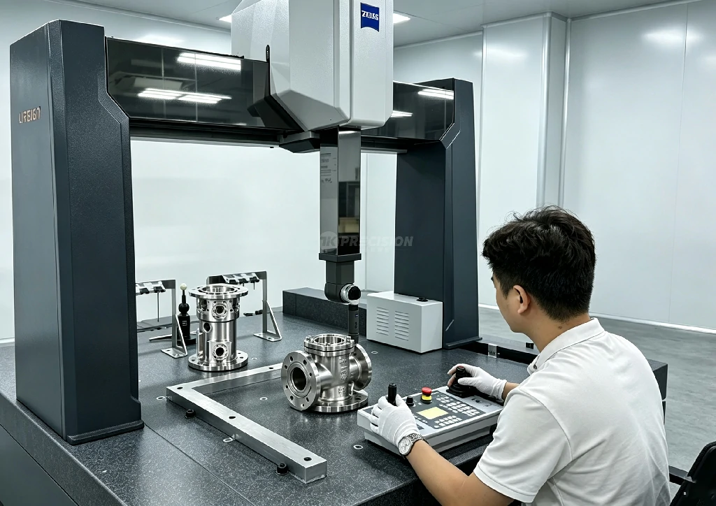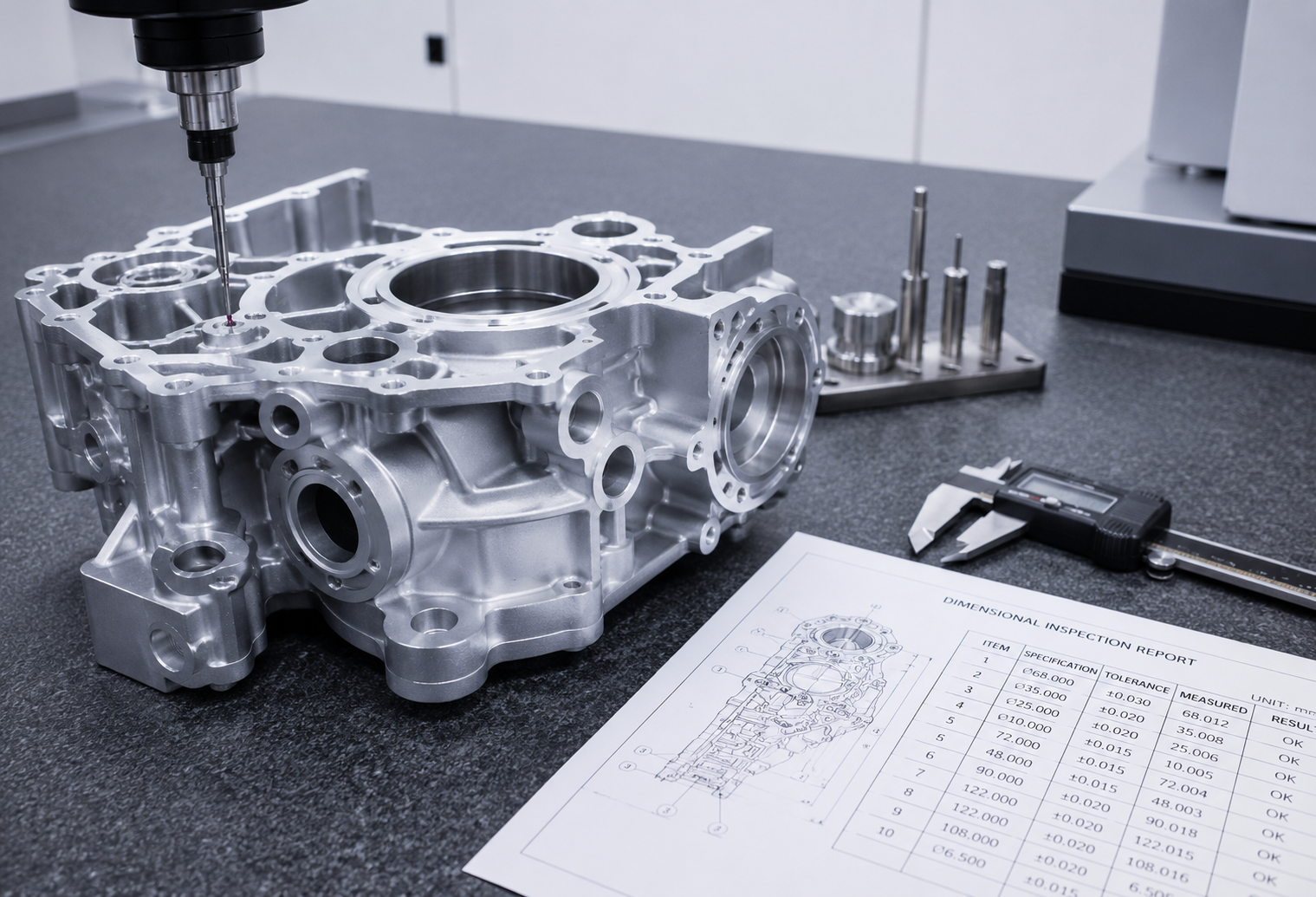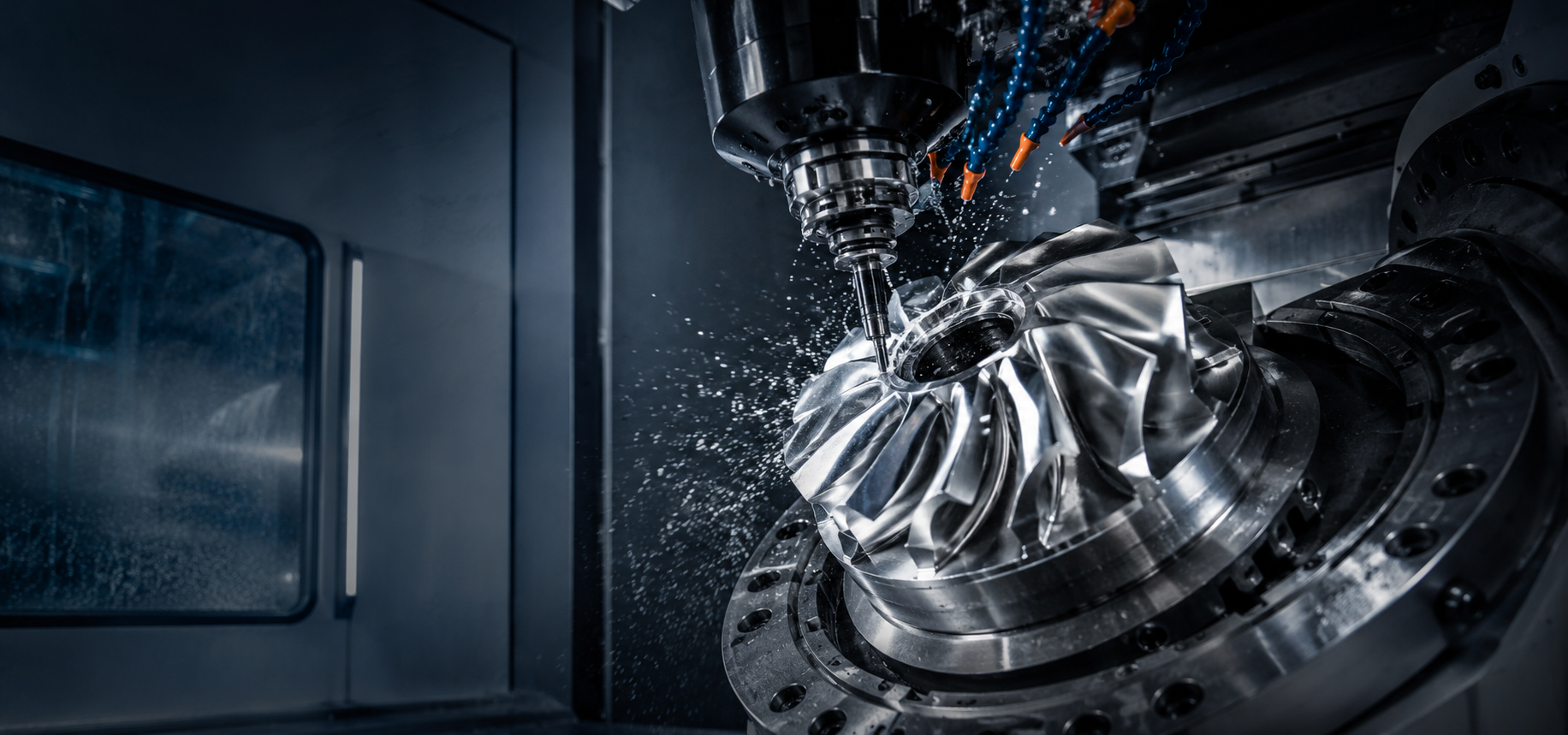
A small design change made early can save multiples in machining cost and time later. DFM (Design for Manufacturability) is about identifying features that significantly increase machining difficulty before the structural design is locked. The following ten principles come from real-world machining experience and are meant for structural engineers to reference during design review.
1. Avoid Extreme Depth-to-Width Ratios in Slots and Holes
When the tool overhang-to-diameter ratio exceeds roughly 4:1 in slot milling, tool rigidity drops and chatter/deflection appear, degrading dimensional accuracy and surface finish. The same applies to deep-hole drilling — depth-to-diameter ratios beyond 10:1 typically require specialized processes like gun drilling, substantially raising cost.
2. Match Internal Corner Radii to Available Tool Radii
Square internal corners cannot be truly sharp with milling — a corner radius matching the tool radius is inherent to the process. Requiring sharp internal corners typically forces a secondary EDM (electrical discharge machining) operation, significantly raising cost. Design internal corner radii no smaller than standard tool sizes (R0.5–R3).
3. Minimize Fixture Reorientations
Every re-fixturing introduces new datum error and adds machining time. Design critical features so they can be machined in a single setup where possible, or at minimum reduce the number of reorientations required.
4. Wall Thickness Must Account for Rigidity and Residual Stress
Thin walls are prone to deformation from cutting forces and internal stress relief during machining. As a general guideline, metal walls should not go below 0.8mm and plastic walls not below 1mm. Avoid abrupt wall thickness transitions (a ratio beyond 3:1 tends to cause sink marks or warping).
5. Avoid Non-Standard Threads and Uncommon Hole Diameters
Prefer standard thread sizes (M3, M4, M5, M6, etc.) and standard drill diameters so off-the-shelf tooling can be used directly. Non-standard sizes often require custom tooling or multiple milling passes, driving up cost and extending lead time.
6. Use Caution With Thin Islands and Overhanging Features
Thin-walled bosses and cantilevered structures are prone to breaking or vibrating under cutting forces. Add supports or transition radii wherever the structural design allows.
7. Clearly Callout Datums — Don’t Let the Shop Decide
Ambiguous datums lead to uncertain fixturing choices, which affect the consistency of critical dimensions. Design should explicitly define both process datums and inspection datums, and keep them consistent whenever possible.
8. Minimize Unnecessary Free-Form Surfaces
Free-form surfaces typically require 5-axis simultaneous machining or finer step-over finishing passes, multiplying machining time. If a surface isn’t functionally required, converting it to a flat plane or simple arc transition can significantly reduce cost.
9. Design Relief Grooves and Clearance Slots Deliberately
Adding relief grooves at shaft shoulders or thread roots avoids interference caused by incomplete corner clearing, and lets the tool maintain stable cutting engagement during direction changes.
10. Account for Dimensional Impact of Heat Treatment and Surface Finishing Early
Processes like quenching, anodizing, and plating change dimensions (anodizing typically adds 5-15 microns of coating thickness). For precision fit dimensions, specify in the drawing whether tolerance applies “before heat treatment” or “after surface finishing” to avoid confusion at acceptance.
Bottom Line
DFM doesn’t limit design freedom — it makes design intent achievable at lower cost and shorter lead time. Before finalizing structural design, invite the machining supplier’s process engineer to participate in a DFM review. This typically surfaces 3-5 optimizable design details before production, which is far cheaper than discovering them after tooling starts.