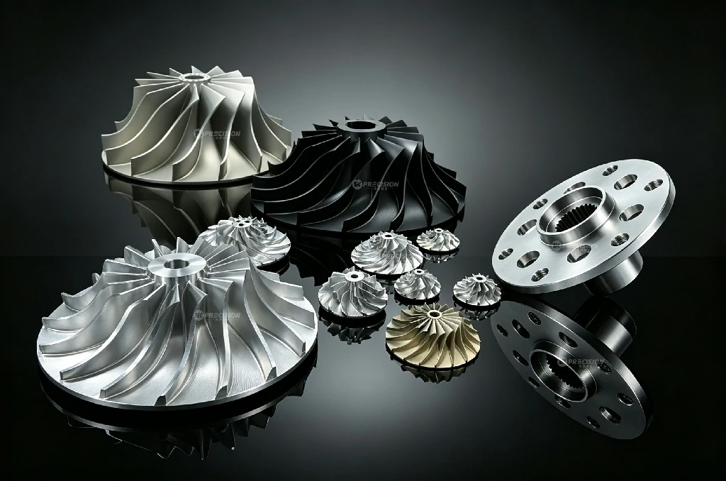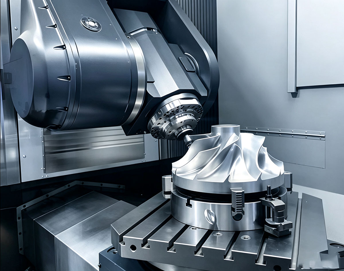
Every experienced CNC machinist knows that impellers occupy a category of their own. The combination of thin blades, deep narrow cavities, tough materials, and unforgiving surface finish requirements creates a perfect storm of manufacturing difficulty. Understanding these challenges — and the proven strategies for overcoming them — separates successful impeller production from costly scrap and missed deadlines.
Challenge 1: Tool Deflection and Vibration
The problem: Impeller inter-blade passages are deep and narrow. The tools required to reach the hub — typically ball end mills with length-to-diameter ratios of 5:1 to 10:1 — are inherently flexible. When a slender tool engages the workpiece, it deflects away from the cut surface and vibrates, producing chatter marks, dimensional inaccuracy, and premature tool failure.
Why it matters: On a blade surface, even 0.02 mm of tool deflection creates a visible surface defect. On the hub floor, deflection causes the tool to cut deeper than programmed, violating the minimum wall thickness.
Solutions:
- Reduce radial engagement: Instead of a conventional 40-50% stepover, use 5-10% in finishing passes. This dramatically reduces cutting forces and, consequently, tool deflection.
- Use barrel or oval-form cutters: These specialized tools have a large radius on the cutting edge but a much smaller shank, providing the surface finish of a large ball end mill with the reach of a small one. The larger contact radius also reduces cusp height at the same stepover.
- Climb milling only: Conventional milling pushes the tool away from the surface; climb milling pulls it toward the surface. For impeller finishing, always use climb milling on both blade faces.
- Toolpath strategy — down-milling: Program finishing passes to machine from the blade tip toward the hub (the stiffer direction). This reduces deflection compared to machining from the flexible tip outward.
- Vibration-dampening tool holders: Hydraulic, shrink-fit, or mechanically damped holders absorb high-frequency vibration that would otherwise transfer to the tool tip.
Challenge 2: Chip Evacuation in Deep Cavities
The problem: As material is removed from inter-blade cavities, chips accumulate. In a deep, narrow space with limited coolant access, these chips are re-cut — causing surface damage, accelerated tool wear, and the risk of chip packing that can break the tool.
Solutions:
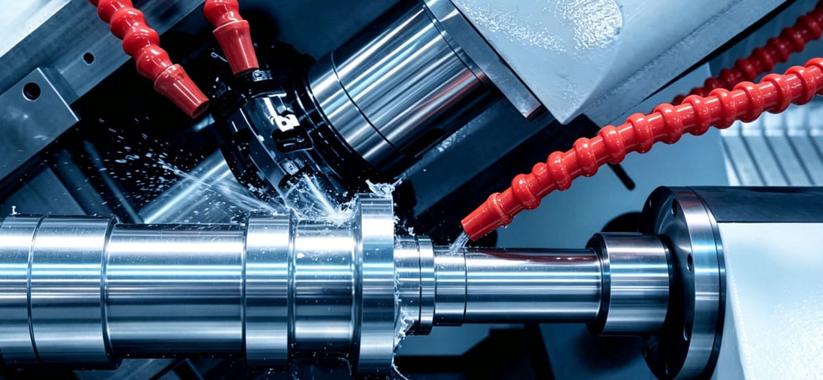
- High-pressure through-spindle coolant (TSC): Coolant delivered at 70-140 bar (1,000-2,000 PSI) through the tool blasts chips out of the cutting zone. This is not optional for deep impeller cavities — it is essential.
- Air blast with minimum quantity lubrication (MQL): For materials where coolant may cause thermal shock (some ceramics, certain aerospace alloys), a high-volume air blast combined with a micro-mist of lubricant can effectively clear chips.
- Peck roughing cycles: Periodically retracting the tool during roughing allows coolant to flush accumulated chips before they can cause problems.
- Orientation strategy: Positioning the impeller so that gravity assists chip evacuation — cavities facing downward during roughing — helps chips fall away from the cut zone.
Challenge 3: Thin Blade Distortion
The problem: As material is removed, residual stresses in the billet are relieved, and the thin blade sections can warp. A blade that is machined to the correct profile at the machine may spring back 0.05-0.10 mm out of tolerance once unclamped. This is especially problematic with materials that have high residual stress — titanium, stainless steel, and wrought aluminum plate (as opposed to forgings).
Solutions:
- Stress-relieved material: Specify stress-relieved billet. For aluminum, T651 temper indicates stress-relieved by stretching. For steel, a normalizing or sub-critical anneal before machining reduces residual stress.
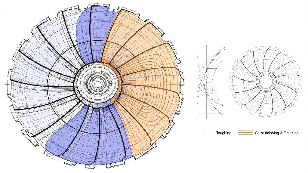
- Symmetrical roughing: Rough both sides of each blade before finishing either side. This balances the stress relief and minimizes asymmetric distortion.
- Multiple intermediate semi-finishing passes: Rather than roughing and then immediately finishing, insert one or two semi-finishing passes that progressively approach the final profile. Each pass relieves a controlled amount of stress.
- Leave the hub for last: Rough the blade profiles first, leaving the hub thick. The thick hub acts as a rigid backbone that resists blade distortion. Finish the hub only after the blades are at final dimension.
- In-process stress relief: For extremely tight tolerance impellers, a thermal stress-relief cycle between roughing and finishing can stabilize the material before final cuts are taken.
Challenge 4: Achieving Required Surface Finish on Blade Surfaces
The problem: Impeller blade surfaces are large, doubly curved areas that must be finished to Ra 0.4-1.6 µm — a surface quality that directly affects fluid flow efficiency. Achieving this on a material like Inconel 718 or Ti-6Al-4V is extraordinarily difficult because these materials gall, smear, and work-harden at the cut surface.
Solutions:
- Optimal cutting parameters: For titanium finishing: 100-150 m/min surface speed, 0.08-0.12 mm/tooth feed, 0.1-0.2 mm depth of cut. For Inconel: 20-40 m/min, 0.05-0.10 mm/tooth, 0.1-0.15 mm depth. These parameters are a starting point — every impeller and machine setup requires fine-tuning.
- Coated carbide tools: AlTiN (Aluminum Titanium Nitride) or AlCrN coatings for titanium; TiAlN or SiAlON ceramic for Inconel. The coating acts as a thermal barrier, preventing the chip from welding to the tool and causing built-up edge that destroys surface finish.
- Constant tool engagement: Sudden changes in tool engagement cause force spikes that leave visible marks on the surface. CAM software with “constant engagement” or “adaptive” toolpaths maintains uniform chip load throughout the cut.
- Dedicated finishing tools: Use a separate, brand-new tool for the final finishing pass — never a tool that has been used for roughing. Tool wear of even a few microns will leave visible lines on the finished surface.
Challenge 5: Inspection Accessibility
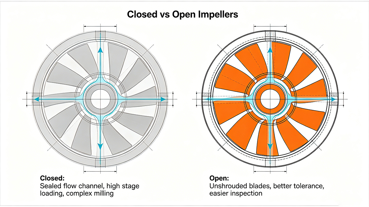
The problem: Closed and even semi-open impellers restrict physical access to internal surfaces. A CMM probe must navigate the same tight spaces as the cutting tool, and some surfaces — the blade pressure side near the hub of a closed impeller — may be completely unreachable by a touch probe.
Solutions:
- Star or disc styli: Multi-tip probe configurations can reach undercuts and behind blades that a single straight stylus cannot.
- Non-contact measurement: Laser scanning and structured-light 3D scanners capture surface data without physical contact, measuring surfaces that a CMM probe cannot reach.
- Replica inspection: For the most inaccessible internal surfaces, a silicone or epoxy replica can be made, extracted, and measured — a technique borrowed from aerospace turbine blade inspection.
- On-machine probing: Integrating a touch probe into the CNC machine itself allows in-process measurement while the part is still fixtured, enabling immediate correction if dimensions drift.
Impeller machining is challenging — but with the right tooling, programming, and process control, it is a challenge that can be met consistently. Tik Precision has invested in the equipment and expertise to produce impellers that meet the most demanding specifications. Contact us about your next impeller project.