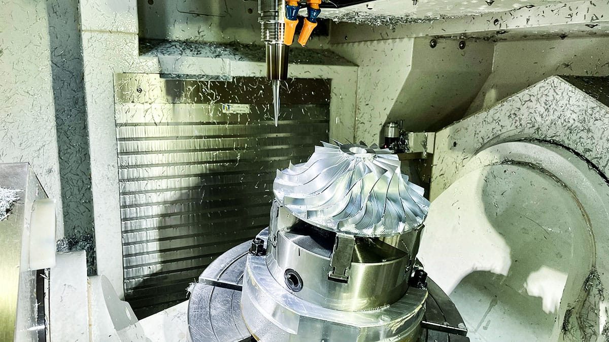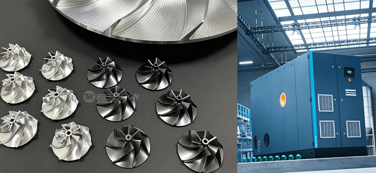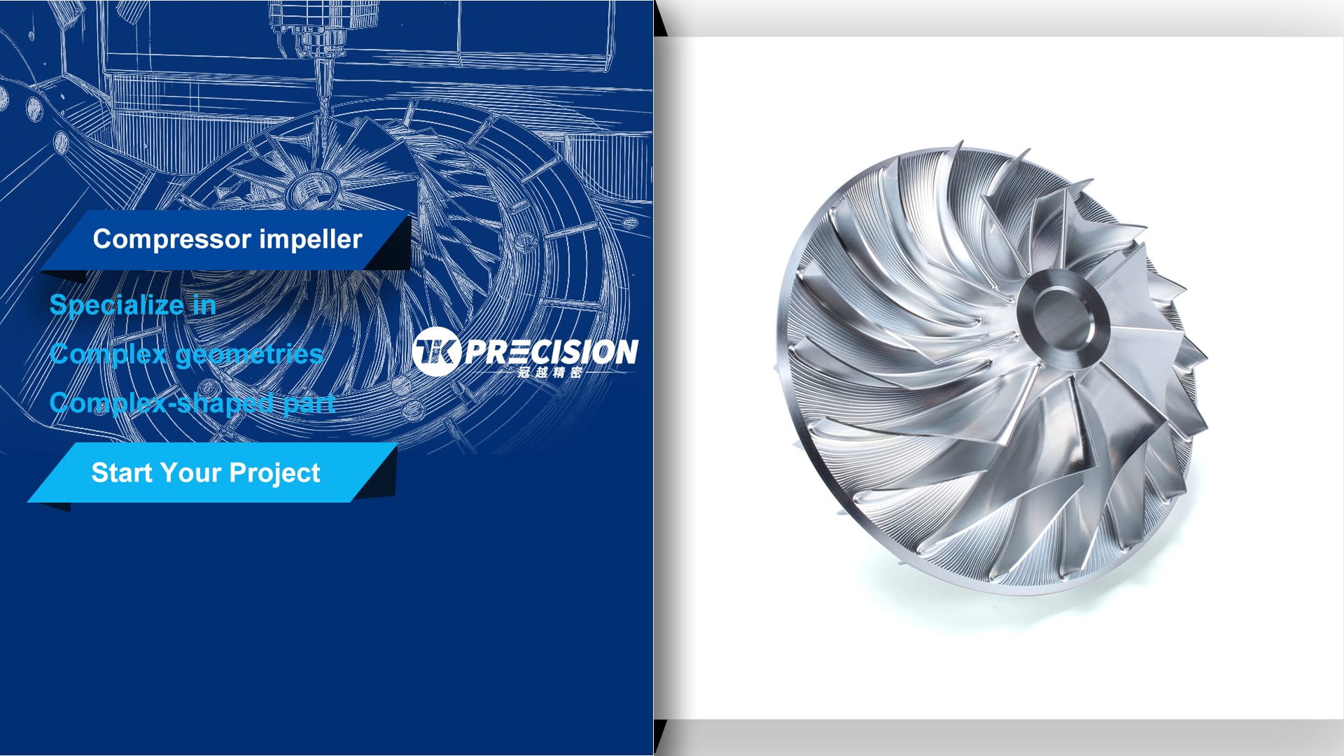
Compressor blades and vanes are the working surfaces that compress air, refrigerant, steam, or gas in everything from oil-free centrifugal compressors to turbochargers and industrial gas turbines. Unlike standard turned parts, a compressor blade is a thin, twisted, aerodynamic profile with tight dimensional requirements. Producing it reliably requires specialist compressor blade CNC machining, controlled processes, and inspection equipment capable of measuring a freeform surface to microns.
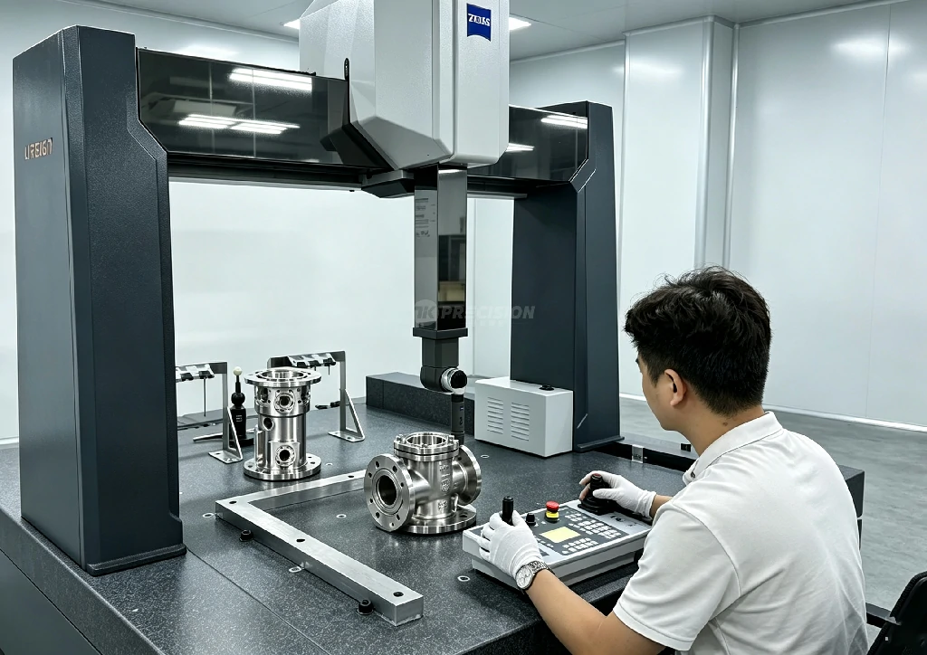
This article walks through the blade machining process from the moment you upload a CAD drawing to the day you receive parts with a full Zeiss CMM inspection report.
Types of Compressor Blades We Machine
“Blade” is a broad term. In compressor engineering, the parts that interact with the flow include:
- Rotor blades — mounted on the rotating impeller or rotor and doing the actual compression work
- Stator vanes — stationary blades that straighten and condition the flow between stages
- Diffuser vanes — positioned around the impeller exit to convert velocity into pressure
- Inlet guide vanes (IGV) — variable or fixed vanes that control compressor capacity
- Splitter blades — shorter blades between full-length impeller blades to improve flow
Each type has its own geometry, fixture requirements, and tolerance priorities, but all share one thing: their aerodynamic profile must match the 3D model.
Why Blades Are Difficult to Machine
A compressor blade concentrates difficulty into a small part:
- Thin, twisted airfoils deflect under cutting force and vibrate during machining
- Leading and trailing edges are delicate and easily chipped or burned
- Stacked section profiles must match the CAD model within tight limits
- Surface finish directly affects efficiency, so tool marks must be minimized
- Material removal is unbalanced, which pulls the part out of tolerance unless fixturing is rigid
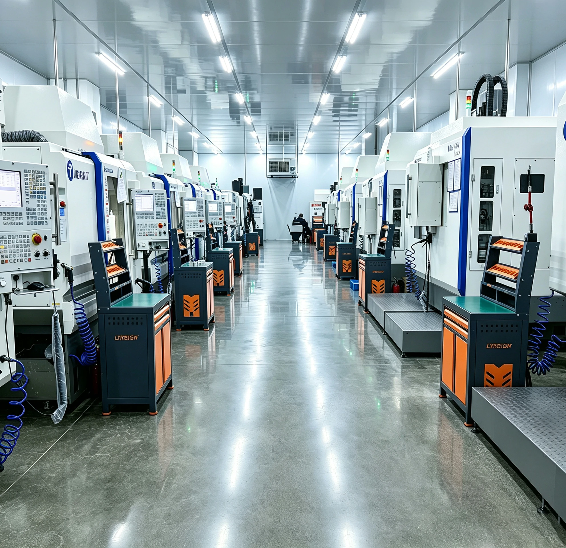
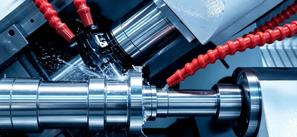
Because of these factors, blade machining is normally performed on simultaneous 5-axis CNC machines using specialized CAM toolpaths rather than on simple 3-axis equipment.
The Blade Machining Process
A typical blade project follows this sequence:
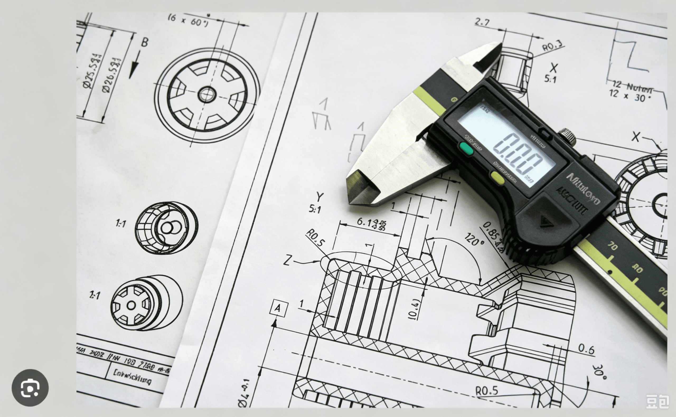
- CAD review and DFM check — engineers verify wall thickness, edge radii, draft, and tolerance realism before quoting.
- Fixturing design — thin blades are clamped at the root or on dedicated soft jaws to avoid distortion.
- 5-axis roughing — bulk material is removed with high-feed strategies that keep heat and stress low.
- 5-axis finishing of the airfoil — constant scallop-height toolpaths produce a smooth profile within tolerance.
- Root, tip, and platform machining — critical mounting features are milled or ground to print.
- Edge blending and deburring — leading and trailing edges are finished to the specified radii.
- Full Zeiss CMM inspection — airfoil sections are scanned and compared against the CAD model.
Materials for Compressor Blades
Blade material is dictated by the operating temperature, medium, and strength requirements:
| Material | Where it is used | Machining consideration |
|---|---|---|
| Aluminum (6061, 7075) | Low-temperature air compressor vanes | Thin sections chip easily; controlled feeds required |
| Stainless steel (304, 316, 17-4PH, 416) | Steam and corrosive media | Work-hardening; sharp tools and rigid setups |
| Titanium (Ti-6Al-4V, TC4) | High-speed, high-strength blades | Poor heat conduction; low speeds, high coolant flow |
| Nickel alloys (Inconel 718, 625) | High-temperature compressors and turbines | Extremely abrasive; premium tooling and slow finishing |
| Precipitation-hardened alloys | Rotor blade applications needing strength + corrosion resistance | Heat treatment sequencing matters |
Tolerances Achievable on Compressor Blades
Tolerance expectations should match the feature:
- Airfoil profile: production tolerance is typically ±0.01 to ±0.02 mm, verified by CMM profile scanning
- Leading and trailing edge radii: controlled within a few hundredths of a millimeter
- Root and platform datums: machined to ±0.005 mm or better where grinding is used
- Surface finish: Ra 0.4 to 0.8 µm on airfoils; finer where specified
Where your drawing demands ±0.002 mm on critical datum features, precision grinding and temperature-controlled machining make it achievable — our DFM team will confirm each feature individually during quoting.
Free DFM Review for Blades
Because blade geometry is expensive to correct after machining, every blade quote includes a free DFM review. Our engineers evaluate:
- Minimum blade thickness relative to depth and tool reach
- Internal fillet radii and channel access for cutters
- Clamping strategy that avoids airfoil distortion
- Whether specified tolerances are achievable on each feature
- Inspection method feasibility for the given geometry
The DFM report gives you a straight answer on cost, risk, and lead time before you commit.
How to Upload Your Blade CAD Drawing
Preparing a blade for quotation is straightforward:
- Export a STEP (.step/.stp) file from your CAD software, plus a 2D PDF with critical tolerances.
- Note the material, quantity, and any coating or surface treatment.
- Upload the files through the website or email them to the engineering team.
- Receive a free DFM review and quotation, typically within one business day.
If you only have a mesh, point cloud, or a physical sample, contact the team — reverse engineering and model rebuild can be arranged under a mutual NDA.
Full-Process Quality Control with Zeiss CMM
Blades must be proven, not assumed. Every blade order ships with:
- Zeiss CMM profile inspection — airfoil sections scanned and compared to the CAD model
- Dimensional reports for root, tip, platform, and datum features
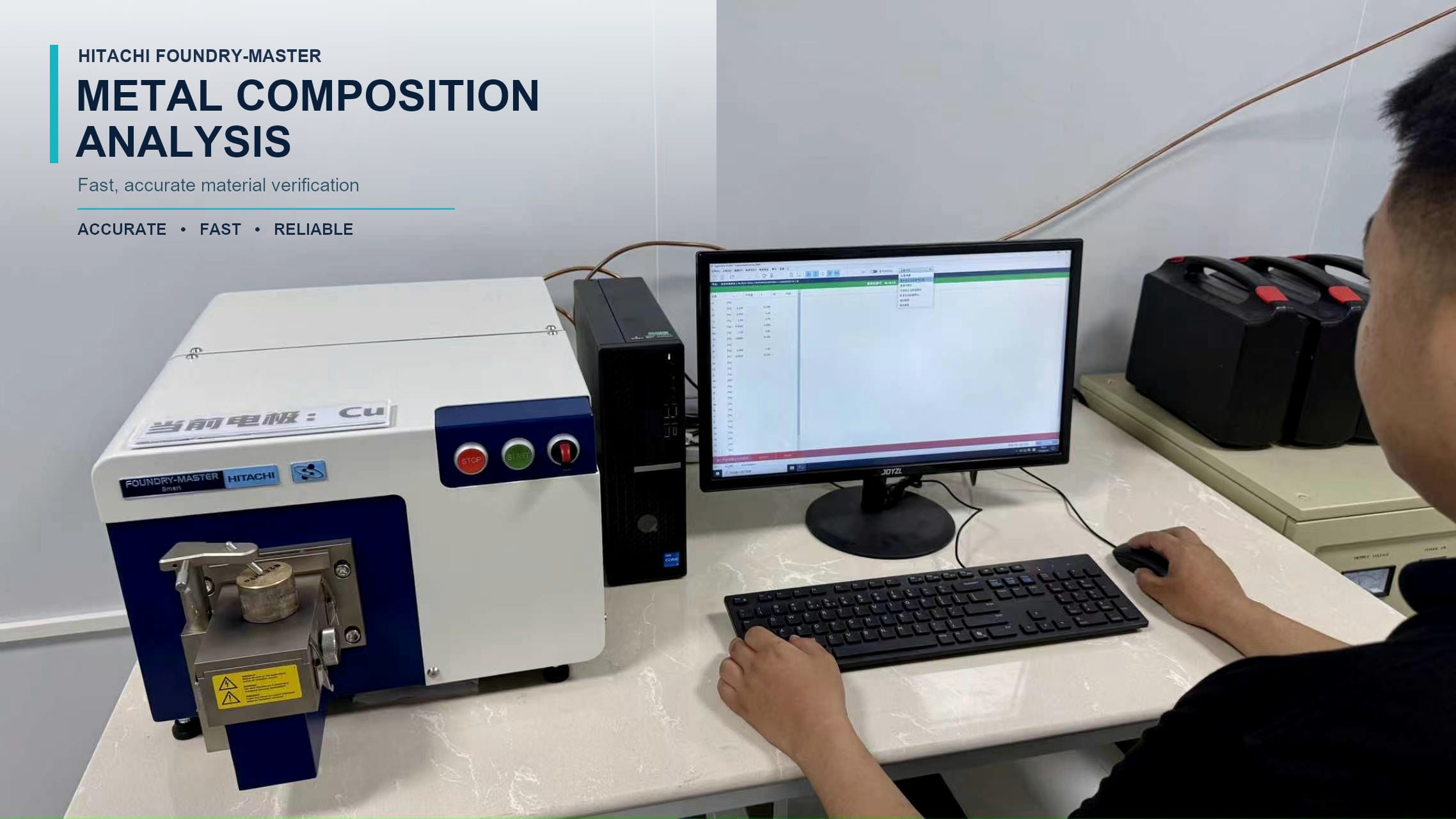
- Surface roughness readings on finished airfoils
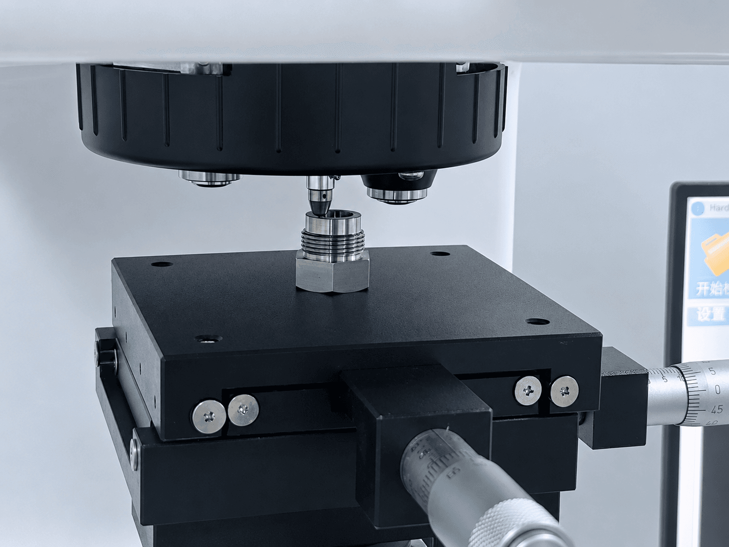
- Material certificates and, where required, hardness or tensile test documentation
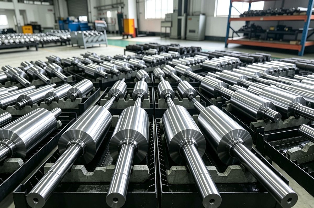
- Full traceability from material batch to final inspection record
This documentation gives your quality team everything needed to release the parts to your assembly line.
FAQ
Can you machine blades from Inconel and titanium?
Yes. We machine nickel-based superalloys and titanium alloys on a daily basis for high-temperature compressor and turbine applications, using 5-axis machines and dedicated tooling.
What is the minimum blade thickness you can machine?
It depends on the material and blade height. As a rule, thicker blades are safer; very thin, tall airfoils may require special fixtures or process changes. The free DFM review will flag any limits on your specific design.
Do you supply CMM inspection reports with blade parts?
Yes. Every blade order includes a Zeiss CMM inspection report with profile deviation data and dimensional results for all critical features.
Can you machine blades from my scanned geometry?
Yes. We can rebuild a machinable solid model from a mesh or point cloud and confirm the geometry with you before production.
How fast can you deliver prototype blades?
Prototype lead times depend on material and complexity, but expedited service is available when needed. Upload your drawing to get a specific lead time for your part.
Upload your blade CAD drawing for a free DFM review and a precision CNC machining quote — including 5-axis machining, ±0.002 mm capability on critical features, and full Zeiss CMM inspection.