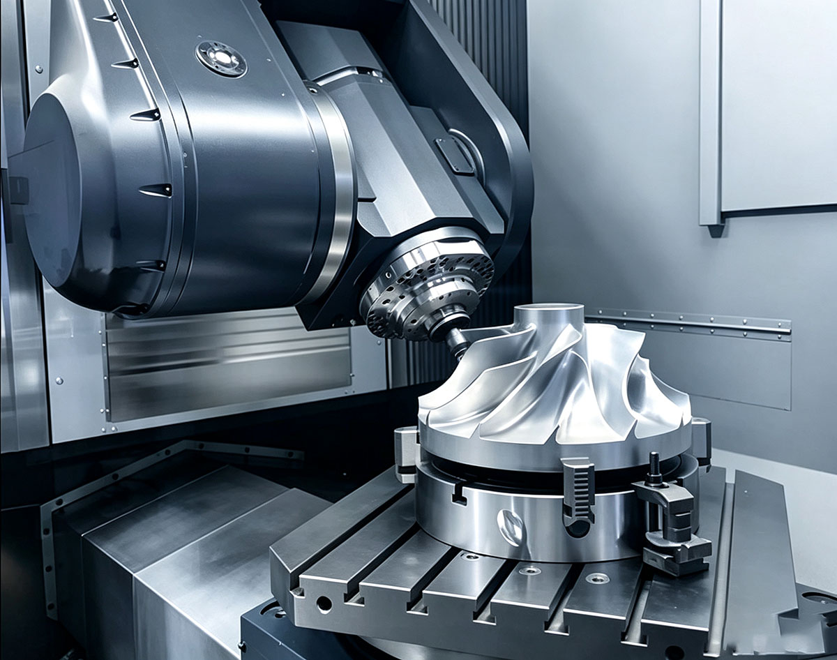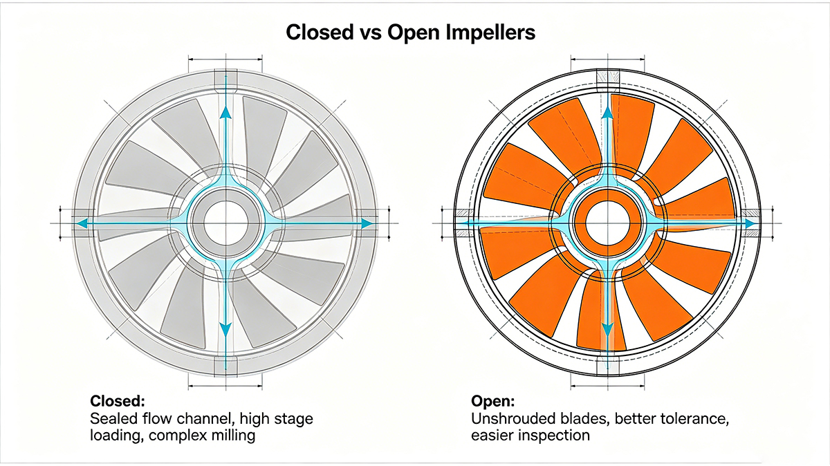
The distinction between closed and open impellers is one of the most fundamental design decisions in rotating equipment. It affects hydraulic performance, manufacturing complexity, cost, and serviceability. Understanding the trade-offs — both in operation and in the machine shop — enables better decisions at the design stage.
What is an Open Impeller?
An open impeller consists of blades attached to a central hub, with no shroud covering the blade tips on either side (or on one side, in the case of a semi-open design). The blades are exposed to the pump casing, with a small running clearance between blade tips and the casing wall.
Advantages of Open Impellers
- Machinability: From a manufacturing perspective, open impellers are dramatically easier to produce. The absence of a shroud means tool access to all blade surfaces is straightforward — the tool can approach from the open side with minimal reach constraints. A semi-open impeller can often be machined on a 4-axis machine.
- Solids handling: Open impellers can pass suspended solids that would clog a closed design. This makes them the preferred choice for wastewater pumps, slurry pumps, and food processing applications where debris is present.
- Cleanability: The exposed blades are easy to clean and inspect. For hygienic applications (food, pharmaceutical), this is a significant advantage.
- Lower manufacturing cost: Simpler geometry means less programming time, shorter cycle times, and lower tooling cost.
Limitations of Open Impellers
- Lower efficiency: Fluid leaks across the blade tip-casing gap, reducing volumetric efficiency by 5-15% compared to a closed design. The precise clearance is critical — too large, and efficiency plummets; too small, and rubbing occurs.
- Recirculation losses: Pressure differential between the pressure and suction sides of each blade drives flow across the tip gap, creating vortices that waste energy.
- Wear sensitivity: As the impeller and casing wear, the tip clearance increases, and efficiency degrades over time. This is particularly problematic in abrasive slurry applications.
What is a Closed Impeller?
A closed impeller features blades fully enclosed between two shrouds — a front shroud (on the inlet side) and a back shroud (on the drive side). Fluid enters through the eye of the front shroud and is contained within the blade passages until discharge. This containment is what gives closed impellers their efficiency advantage.
Advantages of Closed Impellers
- Maximum efficiency: By preventing tip leakage, closed impellers achieve 5-15% higher hydraulic efficiency than open designs at the same diameter and speed. In large industrial pumps operating continuously, this efficiency difference translates to significant energy cost savings.
- Higher pressure capability: The shrouded design enables higher head per stage, making closed impellers the standard for multi-stage pumps and high-pressure applications.
- Axial thrust balance: The back shroud can incorporate pump-out vanes that reduce axial thrust on the bearings, improving reliability.
- Reduced wear sensitivity: Since there is no blade tip-to-casing clearance, efficiency does not degrade from wear at the blade tips. Wear rings at the impeller eye are replaceable.
Limitations of Closed Impellers
- Machining complexity: This is the manufacturing challenge. The front shroud encloses the blade passages, severely restricting tool access. Standard cutting tools cannot reach the internal blade surfaces — the shroud blocks entry from the front, and the hub blocks entry from the back.
- Clogging risk: Solids can become trapped inside the blade passages. Closed impellers are unsuitable for fluids containing suspended particles larger than the blade passage width.
- Higher cost: Complex geometry demands 5-axis machining, specialized tooling, longer cycle times, and more sophisticated CAM programming. A closed impeller can cost 2-4x more to manufacture than a semi-open design of the same diameter.
The Semi-Open Impeller: A Practical Compromise
A semi-open impeller has a back shroud but no front shroud. The blades are exposed on the inlet side but supported at the rear. This design:
- Provides better efficiency than a fully open design (the back shroud eliminates one leakage path)
- Is significantly easier to machine than a closed design (tool access from the open side)
- Offers moderate solids-handling capability
- Is the most common design for general industrial pump applications
Machining Strategy Comparison
| Feature | Open / Semi-Open | Closed |
|---|---|---|
| Minimum axes required | 4-axis (semi-open), 3-axis (open) | 5-axis simultaneous |
| Tool access | Good — open-sided | Severely restricted — internal passages |
| Typical cycle time (200 mm dia.) | 4-8 hours | 12-30+ hours |
| Programming complexity | Moderate | Very high — collision avoidance critical |
| CAM software requirements | General 5-axis capable | Impeller-specific module recommended |
| Inspection method | CMM — direct probe access | CMM + borescope or CT scanning |
How Closed Impellers Are Machined
The most common approach to machining a closed impeller from billet involves two creative strategies:
Strategy 1: Split-Line Manufacturing
The closed impeller is designed as two separate components — a blade-and-hub section and a front shroud. Both halves are machined separately (the blade section as a semi-open impeller, the shroud as a contoured cover), then joined by welding, brazing, or bolting. This is the most economical approach and is widely used for industrial pump impellers up to roughly 500 mm diameter.
- Advantages: Dramatically simplifies machining — both pieces can be produced on 4-axis or 5-axis machines without the extreme reach issues of a one-piece design.
- Disadvantages: The joint introduces a potential failure point. Weld distortion can affect blade tip clearance. Not suitable for the highest-speed applications.
Strategy 2: One-Piece 5-Axis Machining
For the highest-performance applications (aerospace, high-speed turbomachinery), the entire closed impeller is machined from a single billet. This requires:
- Specialized long-reach tapered ball end mills that can fit through the inlet eye and reach the internal blade surfaces.
- Extremely sophisticated CAM programming to navigate the tool through the limited access window without collisions.
- Simultaneous 5-axis motion where the tool and workpiece rotate in coordination while the tool tip tracks the blade profile.
- Extended cycle times: A single closed impeller can require 30+ hours of machine time, much of it spent on the internal blade surfaces.
Whether your application calls for an open, semi-open, or closed impeller design, Tik Precision has the 5-axis machining capability and engineering expertise to deliver. Contact us to discuss your impeller project requirements.