CNC Machining Tolerances: A Practical Guide
CNC machining tolerances define how much a finished part may vary from its specified dimensions. The right tolerance ensures that parts fit, move, seal, and perform as designed. A tighter tolerance can improve performance, but it also requires more machining time, inspection, and process control.
This guide explains common tolerance types, how to choose them, how materials and secondary operations affect accuracy, and which inspection methods verify the final part.
Why Tolerances Matter in CNC Machining
A tolerance should reflect the function of a feature. A cosmetic cover may work with a tolerance of ±0.5 mm. A bearing seat, sealing surface, or precision shaft may require ±0.01 mm or tighter. Applying the tightest tolerance to every dimension increases cost without necessarily improving performance.
Good tolerance planning supports reliable assembly, reduces scrap, shortens lead times, and makes the part easier to manufacture.
Common Types of CNC Machining Tolerances
Linear Tolerances
Linear tolerances control length, width, height, hole diameter, and other dimensional features. For example, a 50 mm dimension with a tolerance of ±0.1 mm must measure between 49.9 mm and 50.1 mm.
Angular Tolerances
Angular tolerances control chamfers, bevels, slopes, and other angled features. An angle of 45° ±1° may vary from 44° to 46°. Angular control is important for mating parts and rotating assemblies.
Geometric Tolerances and GD&T
Geometric Dimensioning and Tolerancing (GD&T) controls form, orientation, location, and runout. Common controls include:
- Flatness: keeps a surface between two parallel planes.
- Perpendicularity: controls the relationship between a surface or axis and a datum.
- Position: defines the location of a feature relative to a datum.
- Cylindricity: controls the roundness and straightness of a cylindrical feature.
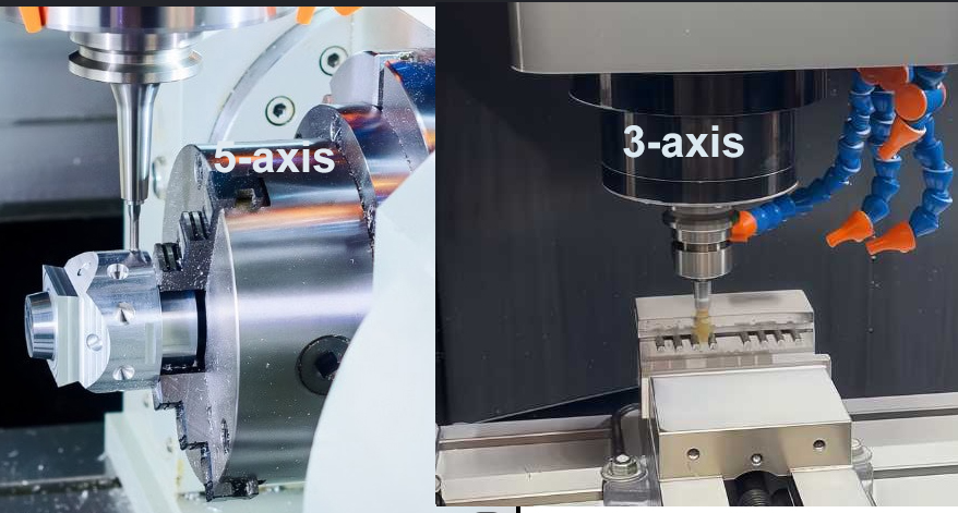
GD&T is especially useful for complex parts, tight assemblies, and multi-axis CNC machining because it communicates functional requirements clearly.
How to Choose the Right Tolerance
Start with Part Function
Identify the features that affect fit, movement, sealing, strength, or alignment. Assign tight tolerances only to those critical-to-function features. Use wider tolerances for non-mating surfaces, cosmetic faces, and relief grooves.
Match the Manufacturing Process
Many CNC machines can achieve general tolerances around ±0.127 mm. With stable equipment, careful setup, tool-wear control, and inspection, tighter tolerances around ±0.025 mm may be possible. Grinding, honing, or lapping may be needed for even tighter diameters and finishes.
Discuss demanding tolerances with your machining partner before finalizing the drawing. This confirms what is achievable and prevents unnecessary cost or rejection risk.
Consider the Material
Material properties influence dimensional stability:
- Aluminum: machines easily but can expand quickly with temperature.
- Stainless steel: can work-harden and may require rigid setups and controlled cutting.
- Plastics: may deform from cutting forces or release internal stress after machining.
- Titanium and nickel alloys: need controlled speeds, coolant, and careful heat management.
Allow for Secondary Operations
Anodizing, plating, coating, and heat treatment can change dimensions. Include these effects in the tolerance plan, or leave machining allowance for post-treatment finishing.
Inspection Methods for CNC Tolerances
Basic Inspection Tools
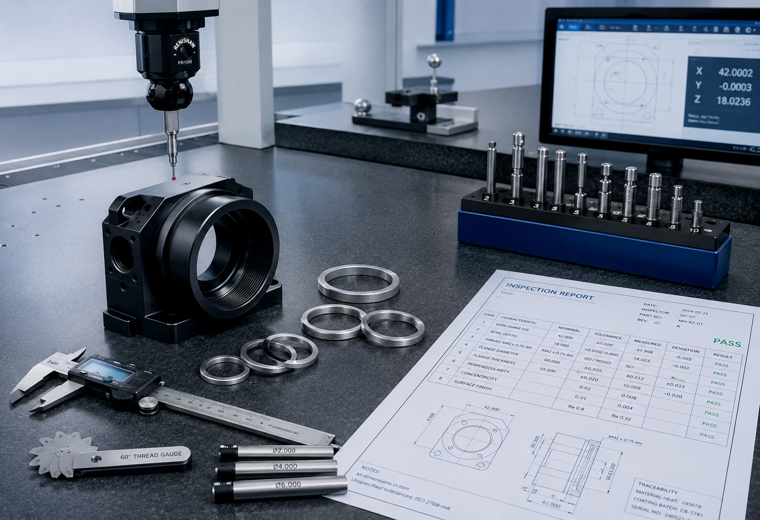
Calipers are suitable for quick checks on general dimensions. Micrometers provide higher accuracy for shafts and smaller features. Height gauges and dial indicators help inspect flatness, parallelism, and perpendicularity.
Advanced Dimensional Inspection
Complex parts and tight tolerances require more advanced equipment:
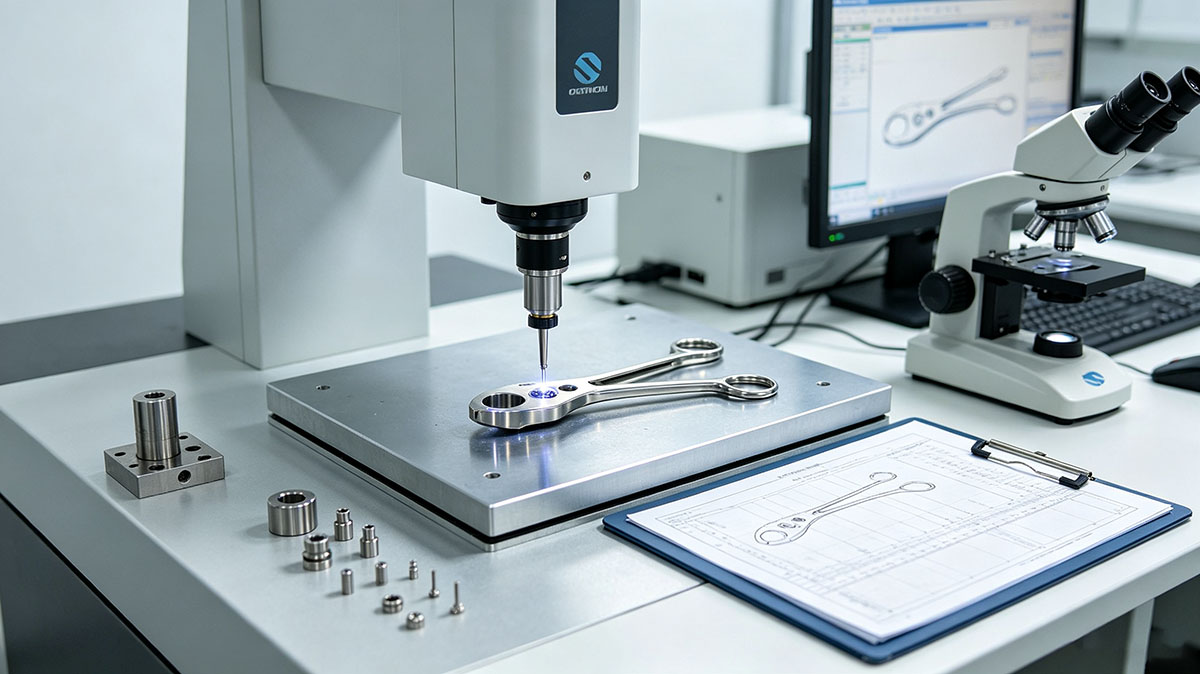
- CMM inspection: captures three-dimensional coordinates for size, position, flatness, roundness, and profile checks.
- Optical comparators: project a magnified profile for visual comparison with a drawing or CAD model.
- 3D scanning: compares freeform surfaces with the original CAD model.
For aerospace, medical, and other regulated applications, inspection reports may include First Article Inspection (FAI), dimensional certificates, measured results, and pass/fail records.
Best Practices for Tolerance Optimization
- Apply tight tolerances only where function requires them.
- Use GD&T to define functional geometry instead of overusing ± dimensions.
- Mark critical-to-function dimensions clearly on the drawing.
- Avoid unnecessarily deep pockets, thin walls, and difficult tool access.
- Keep wall thickness consistent where possible.
- Request a DFM review before production to identify cost and tolerance risks.
Conclusion
Effective tolerance planning balances design performance, manufacturing capability, inspection requirements, and cost. By selecting tolerances according to function and validating them with the right measurement method, you can improve quality while avoiding unnecessary machining expense.
For more guidance, explore our Material Selection Guide for Precision CNC Machining.