Have you received a CNC machined part that looks slightly different from the CAD model or engineering drawing? In many cases, this does not mean the part is defective. The difference may be caused by dimensional tolerances, surface finish, edge conditions, machining allowances, or finishing processes.
This guide explains why CNC machined parts can look different from the drawing while still meeting the functional requirements—and what to specify when appearance is important.
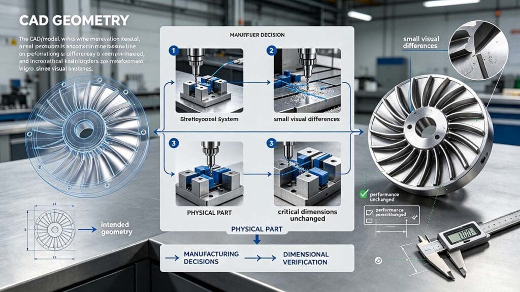
Quick Answer: A CAD Model Shows Design Intent, Not Every Manufacturing Detail
A CAD model represents the intended geometry of a component. To manufacture that geometry, a machinist must select cutting tools, fixtures, tool paths, workholding methods, cutting conditions, and inspection procedures. These manufacturing decisions can create small visual differences without affecting the dimensions or performance that matter.
1. Dimensional Tolerances Allow Controlled Variation
A dimension of 20.00 mm ±0.05 mm allows a finished size between 19.95 mm and 20.05 mm. The manufacturer is not required to produce exactly 20.00 mm; the part only needs to remain within the specified tolerance range.
Different features may also require different tolerances. Tight tolerances should be applied only where they affect fit, alignment, sealing, movement, or performance. Over-tolerancing can increase machining time, inspection requirements, and overall cost.
2. Surface Finish Changes the Way a Part Looks
Two parts can have identical dimensions but appear different because of their surface finish. Tool marks, machining direction, polishing, bead blasting, anodizing, plating, painting, and other treatments can change reflectivity, texture, color, and visual uniformity.
If appearance matters, specify the required surface roughness, finishing process, texture, color, and acceptable cosmetic limits instead of relying on the CAD model alone.
3. Edge Breaks and Chamfers May Be Added for Safety
Sharp edges are often removed to improve handling, prevent damage, and make the part safer to assemble. A manufacturer may apply a standard edge break or chamfer when the drawing does not define a sharp edge.
Critical edges—such as sealing edges, locating edges, cutting edges, and assembly interfaces—should be dimensioned clearly. You can also state whether edge breaks are allowed and define their size and tolerance.
4. Manufacturing Allowances Can Affect Intermediate Parts
Some components are intentionally produced with extra material before grinding, polishing, coating, heat treatment, or another secondary operation. This machining allowance may make an intermediate part look different from the final CAD geometry.
Drawings should identify which dimensions apply before and after secondary processes so that the manufacturer and inspection team evaluate the correct stage of production.
5. The Drawing May Not Define Cosmetic Requirements
Engineering drawings usually communicate function, dimensions, materials, and tolerances. They may not fully define visual expectations. If the part will be visible to customers or used in a premium product, include requirements for:
- Surface roughness and texture
- Tool marks and machining direction
- Color and coating
- Scratches, dents, stains, and other cosmetic defects
- Edge conditions and corner radii
- Inspection lighting and acceptance criteria
- Reference photos or approved samples
How to Prevent Problems Before CNC Machining
- Identify critical dimensions and functional surfaces.
- Apply tolerances based on actual fit and performance requirements.
- Define surface finish, coating, edge breaks, and cosmetic standards.
- Confirm whether dimensions apply before or after finishing.
- Request a design-for-manufacturing review before production.
- Provide both the 2D drawing and the latest 3D CAD model.
When Should You Request a DFM Review?
A DFM review is useful when a part has unusually tight tolerances, complex features, thin walls, deep pockets, difficult-to-machine materials, demanding cosmetic requirements, or multiple finishing processes. Early review can help prevent rework and identify specifications that increase cost without improving function.
Conclusion
A CNC machined part can look different from a drawing or CAD model and still be correct if it meets the specified dimensions, tolerances, material, surface finish, and functional requirements. Clear documentation is the best way to align design, manufacturing, and inspection expectations.
Need Help Reviewing Your CNC Drawing?
Send your 2D drawing and 3D CAD model for a project-specific DFM review. Our engineering team can help evaluate tolerances, surface finishes, manufacturing processes, inspection requirements, and quotation considerations before production begins.