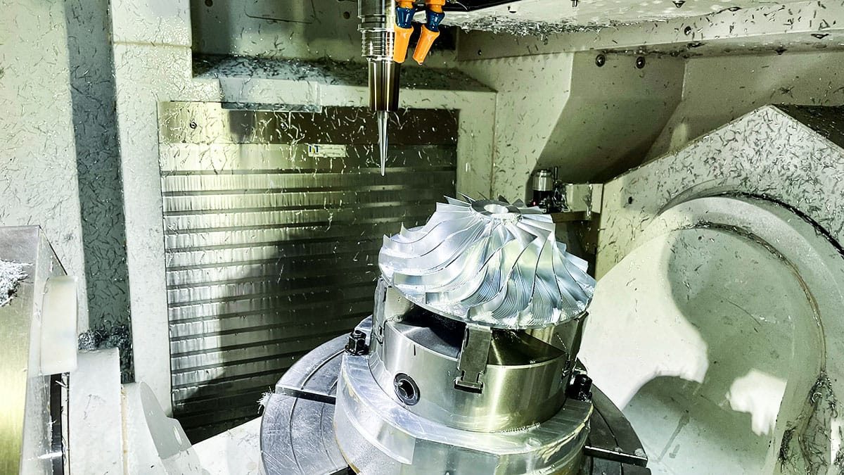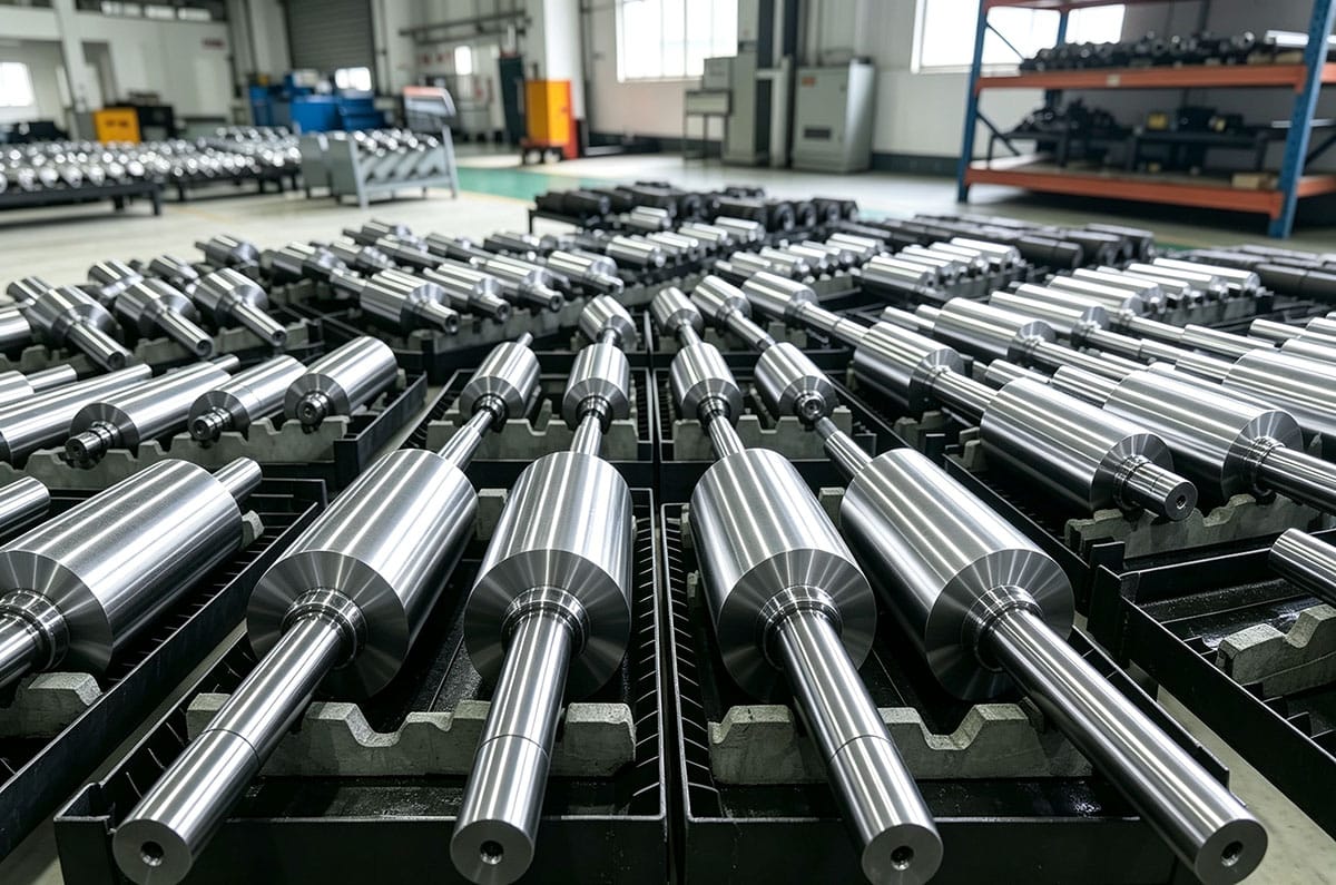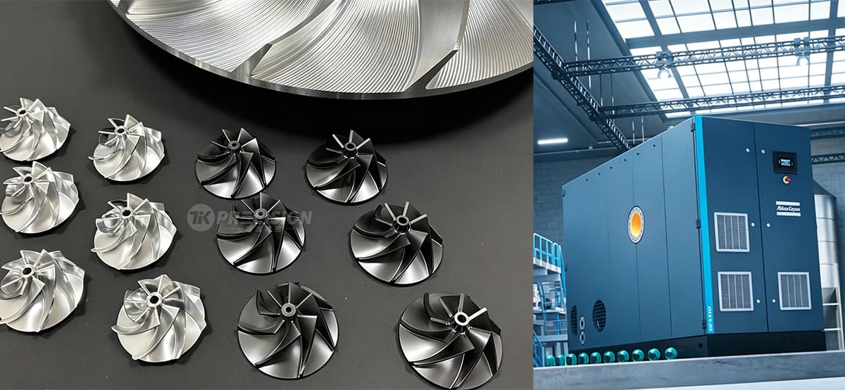
The rotor is the rotating heart of a compressor. It carries the impellers and blades, transmits torque, and must spin smoothly at very high speeds for thousands of operating hours. A poorly machined rotor creates vibration, overheats bearings, and shortens the life of the entire machine — which is why precision CNC machining of compressor rotors is one of the most demanding jobs in rotating equipment manufacturing.
In this guide, we explain how rotors are machined to print, how tolerances like runout and concentricity are controlled, how dynamic balancing fits into the process, and what documentation you should expect with every rotor you order.
What Makes a Compressor Rotor Difficult to Machine
A compressor rotor is essentially a long, slender shaft with precision features along its entire length:
- Multiple bearing journals that must be concentric with each other and with the axis of rotation
- Impeller seats and seal diameters with tight interference and runout requirements
- Splines, keyways, and coupling fits that transmit torque
- Long overall length that increases deflection and makes holding straightness difficult
- Balancing requirements that force every stage of machining to remove material predictably
Because the rotor defines the rotation axis of the whole machine, every feature must be machined relative to that axis — which is why rotor work is usually done between centers, on precision lathes, and finished with grinding.
The Rotor Machining Process
A typical precision rotor project moves through these steps:
- Material preparation — forged or bar stock is verified for material grade, hardness, and straightness.
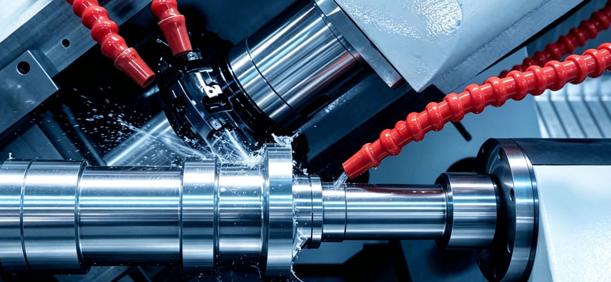
- Center drilling and turning — the rotor is turned between centers so that all diameters share one common axis.
- Rough turning — excess material is removed in stages to relieve stress and avoid distortion.
- Semi-finish turning — critical diameters are brought near final size with controlled stock remaining.
- Heat treatment (where specified) — hardening or stress-relieving steps are sequenced before finishing.
- Precision grinding — journals, seal diameters, and seats are ground to final tolerance and finish.
- Spline, keyway, and thread machining — performed on mill-turn centers or dedicated equipment.
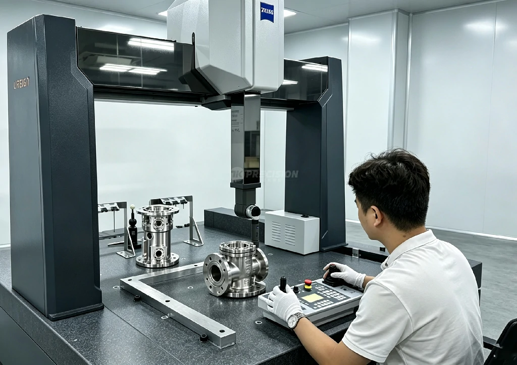
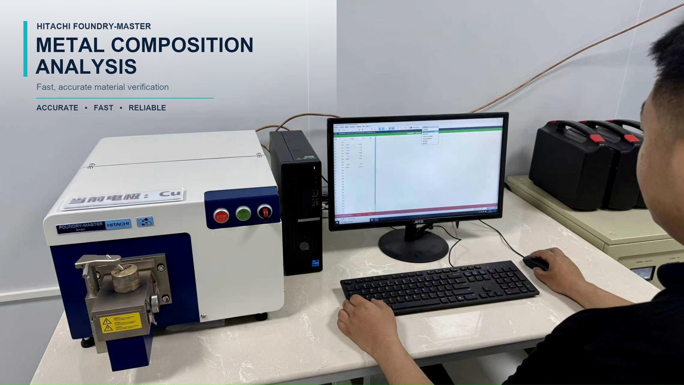
- Final inspection and balancing — Zeiss CMM verification followed by dynamic balancing if required.
The key principle throughout: reference everything to the rotation axis, not to a datum on the outside of the part.
Tolerances Achievable on Compressor Rotors
Rotor tolerances are among the tightest in mechanical engineering:
- Journal diameters: ±0.002 mm achievable with precision grinding under controlled temperature
- Runout (TIR): 0.005 mm or better on critical journals
- Concentricity between journals: verified by measuring on centers or between V-blocks
- Cylindricity and roundness: controlled within microns on ground diameters
- Surface finish: Ra 0.2–0.4 µm on bearing journals
- Balance quality: G2.5 or better, per ISO 21940, depending on the application
These capabilities are why rotor manufacturing and precision grinding are treated as separate disciplines from standard CNC turning.
Materials for Compressor Rotors
Rotor material must combine strength, fatigue resistance, and dimensional stability:
| Material | Typical rotor applications | Notes |
|---|---|---|
| Alloy steel (4140, 4340) | General industrial compressors | Quenched and tempered for strength |
| Stainless steel (410, 420, 17-4PH) | Corrosive or wet media | Hardened after machining, ground to finish |
| Nitriding steels (e.g., 38CrMoAl) | High-speed shafts needing wear resistance | Nitrided journals for hardness and fatigue life |
| Duplex and super duplex stainless | Offshore and chemical service | Excellent corrosion resistance |
| High-strength low-alloy steels | Oil-free and high-speed machines | Requires careful heat treatment sequencing |
Material certificates and, where specified, mechanical test reports are provided with each rotor.
Dynamic Balancing: Why It Matters
At high speed, a rotor that is dimensionally perfect but unbalanced will still vibrate. Dynamic balancing corrects mass distribution around the rotation axis:
- Two-plane balancing is standard for long rotors, correcting both static and couple unbalance
- Balancing quality grades follow ISO 21940-11, with G2.5 commonly specified for compressor rotors
- Balancing reports document residual unbalance in gram-millimeters (g·mm) per plane
- Correction methods include drilling, milling, or adding balance weights in designated planes
When rotors ship with a balancing report, your assembly team can install them with confidence that vibration levels will be within specification.
Free DFM Review for Rotor Projects
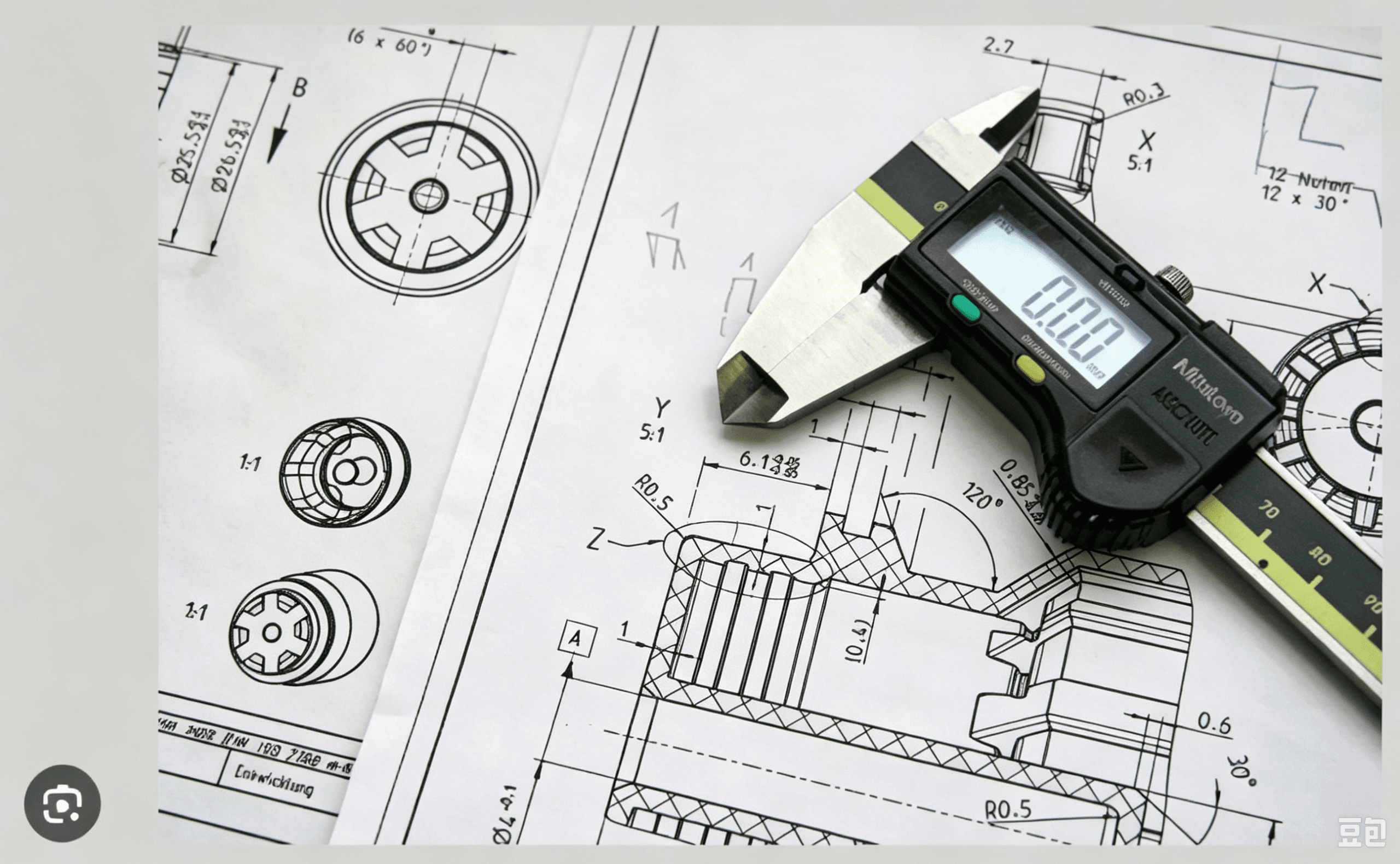
Before any rotor is cut, the engineering team reviews your drawing for free:
- Wall thickness between bores and keyways
- Stress concentration at step changes in diameter
- Achievable runout and concentricity for the part length
- Fixturing and between-centers strategy
- Grinding stock and heat treatment sequencing
The DFM report identifies risks early so that the rotor you receive is the rotor you designed — not a compromise.
Upload Your Rotor Drawing and Get a Quote
Rotor quotations are straightforward when the drawing is complete:
- Upload a STEP file and 2D PDF showing all critical tolerances, materials, and heat treatment notes.
- Specify quantity, balancing grade, and inspection requirements.
- Receive free DFM feedback and a quotation with a confirmed lead time.
- Approve to release — programs, fixtures, and inspection plans are then prepared.
For existing rotor designs that need repair or remanufacture, the team can also work from physical samples and reverse-engineered models.
Quality Documentation for Every Rotor
A precision rotor is only as good as its documentation. Every rotor order includes:
- Zeiss CMM inspection report covering journals, seats, splines, and critical dimensions
- Runout and roundness measurements recorded on the final part
- Surface roughness results on ground diameters
- Dynamic balancing report (when balancing is specified)
- Material certificates with heat number traceability
This complete record lets your quality department close out the order without chasing paperwork.
FAQ
What is the tightest runout you can hold on a compressor rotor?
On ground journals, total indicated runout (TIR) of 0.005 mm or better is achievable under controlled conditions. The DFM review will confirm what is realistic for your specific rotor length and design.
Do you balance rotors in-house?
Yes. Dynamic balancing is performed on precision balancing machines, and the residual unbalance report is supplied with the parts.
Can you machine a rotor from a worn or damaged sample?
Yes. We can reverse engineer a machinable model from the sample, confirm critical dimensions with you, and manufacture a replacement or improved version.
What materials do you machine rotors from?
Common rotor materials include alloy steels, martensitic and precipitation-hardening stainless steels, nitriding steels, and duplex stainless steels.
How do you control straightness on long rotors?
Rotors are machined between centers and inspected on centers so that straightness, runout, and concentricity are all referenced to the true rotation axis. Stress-relief and staged roughing also control distortion.
Upload your rotor CAD drawing for a free DFM review and precision CNC machining quote — including grinding to ±0.002 mm, dynamic balancing, and full Zeiss CMM inspection reports.