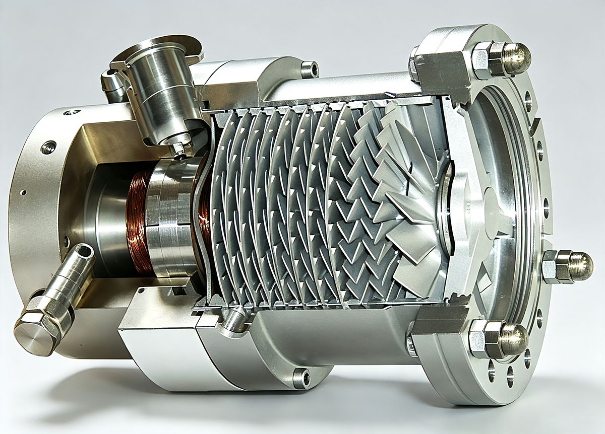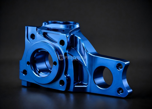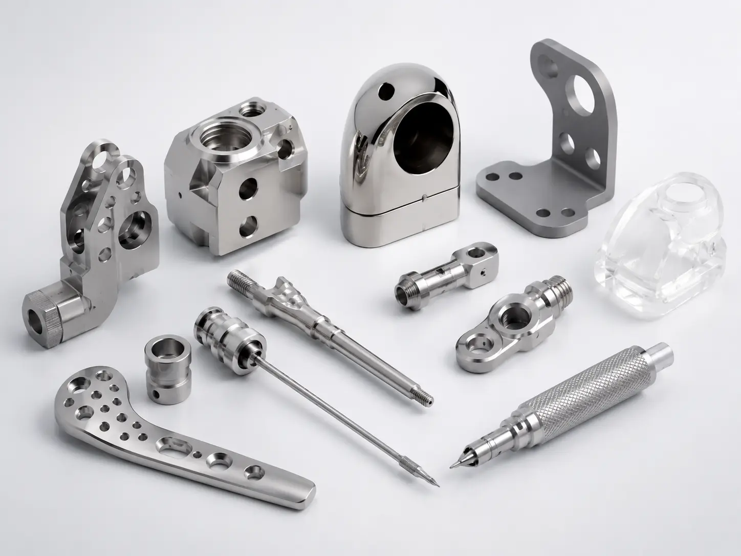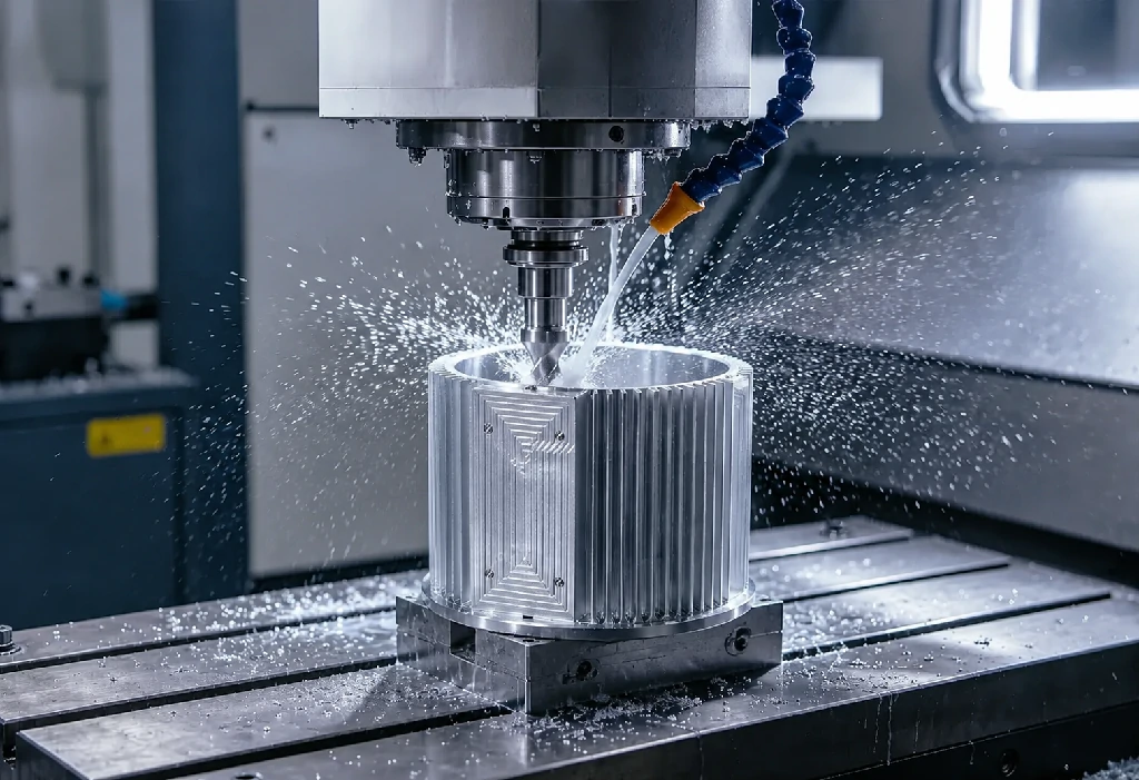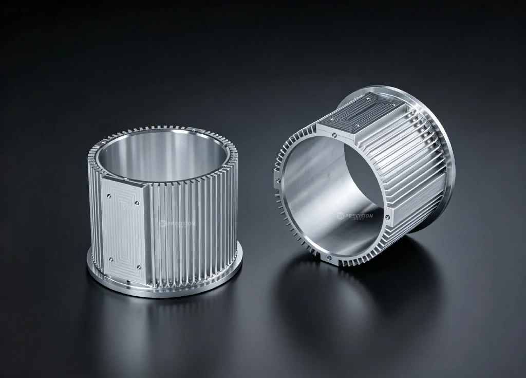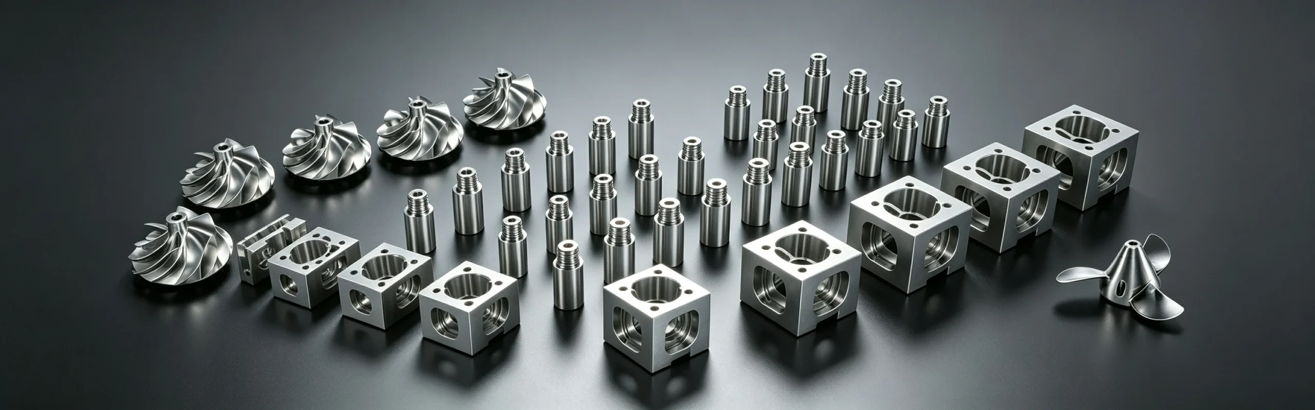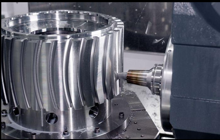
The hub (or centerbody) of a ducted fan is the structural heart of the rotating assembly. It supports the blades against centrifugal and aerodynamic loads, transmits torque from the drive motor through the spindle or shaft, and positions the fan precisely on the axis of rotation. The hub must be strong, stiff, exactly balanced, and — in many designs — aerodynamically shaped to minimize flow losses at the blade roots. This article covers the CNC machining of ducted fan hubs, spindles, and related rotating components.
Hub Design Configurations
Integral Blade-Hub (Blisk) Design
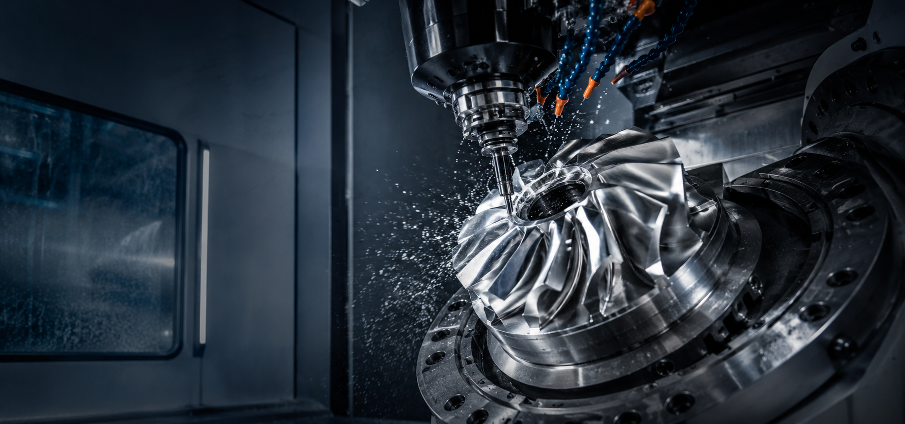
The blades and hub are machined from a single piece of material — a blisk (bladed disk). This design eliminates the mechanical joints between blades and hub, reducing weight, eliminating potential fretting or loosening, and enabling thinner, more efficient blade root sections that don”t need to accommodate fasteners or dovetail slots. The downside: damage to a single blade requires replacement of the entire rotor, and machining the complete blisk demands 5-axis capability with challenging tool access in the inter-blade region near the hub.
Separate Blade and Hub (Inserted Blade) Design
Individual blades are attached to the hub using dovetail slots, fir-tree roots, threaded fasteners, or bonding (adhesive). This allows individual blade replacement and the use of different materials for blades and hub. The machining of the hub involves creating precise blade attachment features — dovetail slots, threaded holes, or bonding surfaces — at accurate angular positions.
Hub Machining: Features and Tolerances
| Feature | Description | Typical Tolerance | Machining Method |
|---|---|---|---|
| Bearing bore | Precision bore for mounting the hub on the spindle or directly on the motor shaft | Diameter H6 or H7 (e.g., 25.000/25.013 mm); roundness 0.005 mm; concentricity 0.01 mm to hub OD | CNC turning or jig boring; honing for final size and surface finish |
| Shaft bore keyway or spline | Positive torque transmission feature | Keyway width ±0.01 mm; symmetry 0.02 mm to bore centerline. Spline: per ANSI B92.1 or DIN 5480 | Broaching, wire EDM, or slotting on a mill-turn; splines: gear hobbing, shaping, or broaching |
| Hub OD (blade attachment diameter) | The cylindrical surface from which blades extend | Diameter ±0.02 mm; roundness 0.015 mm | CNC turning |
| Dovetail slots (for inserted blades) | Precision slots at the hub OD that capture the blade root | Profile ±0.01 mm; angular spacing ±0.05°; slot axis parallel to hub axis within 0.01 mm over slot length | Broaching (production), wire EDM (low volume, high precision), 5-axis milling with lollipop or T-slot cutters |
| Blade location faces (integral blade design) | The hub surfaces between blades that form the inner flow path | Profile ±0.05 mm to CAD; surface finish Ra 0.8 µm | 5-axis ball end mill finishing as part of the integrated rotor machining sequence |
| Balance correction features | Surfaces where material can be removed for dynamic balancing: end faces, OD flanges, or dedicated balance rings | Lightweight machining; may require re-spin verification | Drilling, milling, or grinding — dictated by balance machine output |
| Threaded holes (for nose cone, balance weights, or blade retention) | Helicoil or threaded inserts in aluminum hubs for steel fastener compatibility | Thread class 6H; position ±0.1 mm; perpendicularity 0.05 mm to mounting face | CNC drilling and tapping; thread milling for critical threads or hard materials |
Spindle / Shaft Machining
The spindle (or shaft) connects the hub to the drive motor and runs in the ducted fan”s bearings. It is typically a stepped cylindrical shaft with bearing journals, seal surfaces, a hub mounting feature (taper, flange, or keyed section), and a drive coupling feature.
Spindle Features and Tolerances
- Bearing journals: Ground or hard-turned surfaces with diameter tolerance of IT5 (e.g., 25.000/25.009 mm for a 25 mm journal), roundness 0.003 mm, surface finish Ra 0.2-0.4 µm. The two bearing journals (front and rear) must be concentric within 0.005 mm TIR.
- Hub mounting taper or spigot: A short taper (1:10 to 1:20) or a spigot diameter with a face that locates the hub concentrically. Taper angle tolerance ±0.01° ensures full contact area for torque transmission. Concentricity to bearing journals within 0.01 mm.
- Seal surfaces: The surface where a radial shaft seal or labyrinth seal contacts (or runs in close proximity to) the shaft. Surface finish Ra 0.2-0.4 µm with a non-directional or helical “pump” finish (for hydrodynamic seals). Hardness typically > 50 HRC — achieved by hardening and grinding, or by hard-turning with CBN tooling.
- Threaded sections: For the hub retaining nut. Thread class 6g for general threads; 4h for precision applications. Thread axis concentric to bearing journals within 0.02 mm TIR. Thread rolling (rather than cutting) produces stronger threads with favorable fatigue properties — important for highly loaded spindles.
- Drive coupling feature: Keyway, spline, or flexible coupling hub interface at the spindle”s motor end. Positioned opposite the hub end to minimize the distance between bearings and the fan”s center of mass (overhung load).
Spindle Manufacturing Sequence
- Center drill both ends of the bar stock — centers are the primary datum for all subsequent turning operations
- Rough turn the full spindle profile, leaving 1-2 mm stock on all surfaces
- Stress relieve (if required for the material — e.g., after heavy roughing of alloy steels)
- Semi-finish turn, leaving 0.3-0.5 mm stock for grinding or hard turning
- Heat treat (case hardening, induction hardening, or through-hardening per material specification)
- Grind or hard-turn bearing journals and seal surfaces to final size and finish
- Mill keyways or cut splines (post-grinding to maintain concentricity)
- Dynamic balance (the spindle alone, then the spindle-hub assembly)
Material Selection for Hubs and Spindles
| Component | Common Materials | Rationale |
|---|---|---|
| Hub (aluminum fan) | 7075-T6, 7075-T73, 6061-T6 | High strength-to-weight ratio; matches blade material; anodized for corrosion and wear resistance |
| Hub (titanium fan) | Ti-6Al-4V | Matches blade material; high strength; used in high-temperature or corrosion-resistant applications |
| Hub (steel fan) | 17-4PH, 4340, 300M | Very high strength for extreme speed / load applications |
| Spindle (general) | 4140, 4340, 8620 (case-hardened) | Good fatigue properties; hardenable for bearing and seal surfaces; readily available |
| Spindle (high-speed) | 300M, Aermet 100, Custom 465 | Ultra-high-strength steels for high centrifugal loads; used in high-performance UAV and turbomachinery applications |
| Spindle (corrosion-resistant) | 17-4PH, 15-5PH, Nitronic 60 | Precipitation-hardening stainless steels with good strength and corrosion resistance |
Quality Verification
- Bearing journal inspection: Diameter measured with a calibrated micrometer or high-resolution CMM. Roundness measured with a roundness tester (Talyrond or equivalent). Surface finish with a stylus profilometer — Ra, Rz, and Rmax (bearing manufacturers often specify Rmax as it captures the deepest valley that could initiate a fatigue crack).
- Concentricity of hub ID to hub OD: Mount the hub on an expanding mandrel centered on the hub bore, and indicate the hub OD. Any TIR indicates eccentricity between the bore and the OD, which translates directly to mass unbalance when the rotor runs.
- Dovetail slot inspection: A dedicated go/no-go gauge for the dovetail profile, plus a CMM check of angular spacing. For fir-tree root forms common in turbomachinery, custom CMM programs compare the measured profile to the nominal CAD profile.
- Dynamic balance of the hub-blade assembly: The complete rotating assembly (hub + blades) is dynamically balanced to ISO G2.5 or better. This is the final quality gate for the rotor — any unbalance that cannot be corrected within the available correction surfaces is cause for rework.
Tik Precision machines ducted fan hubs and spindles on our CNC turning and 5-axis milling platforms, with in-house dynamic balancing and CMM inspection. From small aluminum UAV hubs to large steel industrial fan spindles, we provide the precision and reliability your design demands. Contact us to discuss your hub or spindle requirements.