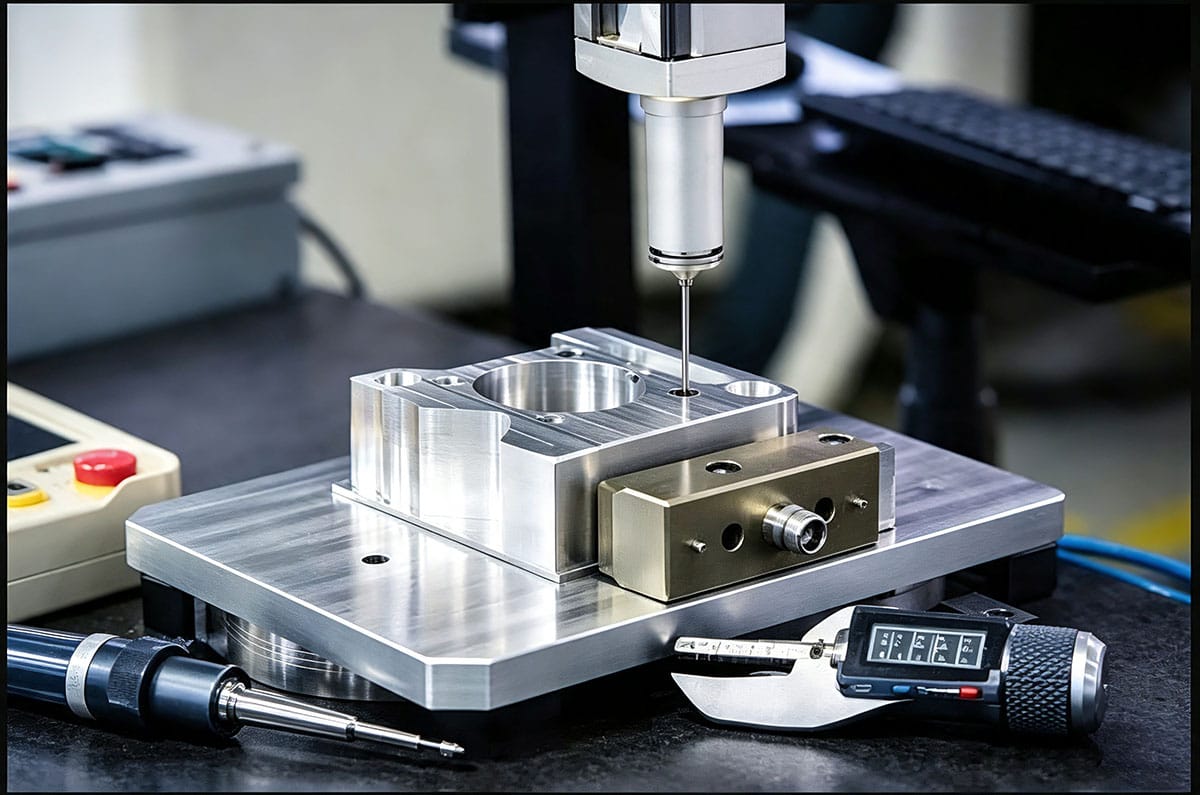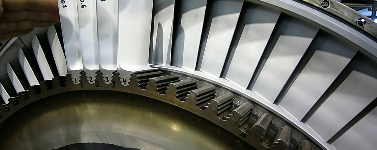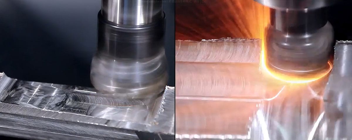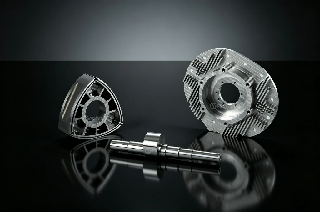
Ducted fans — also known as shrouded propellers or ducted rotors — represent a specialized category of fluid-moving machinery in which a rotating fan operates within a closely fitting cylindrical duct or shroud. Compared to open propellers of equivalent diameter, ducted fans deliver higher static thrust efficiency, reduced tip losses, lower noise, and enhanced safety from shrouded blades. These advantages have made ducted fans indispensable in UAV propulsion, VTOL aircraft, hovercraft, air cushion vehicles, industrial blowers, wind tunnels, and HVAC systems. The CNC machining of ducted fan components demands expertise across a range of disciplines: aerodynamic blade geometry, thin-wall structural machining, tight-clearance housing fabrication, and precision assembly.
The Aerodynamic Rationale for Ducted Fans
The fundamental benefit of a duct is that it suppresses the formation of the wingtip vortex at the blade tip. In an open propeller, the pressure difference between the pressure and suction surfaces of the blade drives a tip vortex that reduces effective blade span, introduces induced drag, and generates noise. The duct physically blocks this vortex formation. The result is a fan that can operate at higher blade loading (more thrust per unit of blade area) without flow separation.
Additionally, the duct itself can generate thrust. As the fan accelerates air through the duct, the reduced static pressure on the inner surface of the duct inlet lip creates a forward-acting pressure force — duct thrust. In a well-designed ducted fan, the duct can contribute 30-50% of the total static thrust.
Key Components and Their Manufacturing Requirements
| Component | Function | CNC Manufacturing Method | Key Requirements |
|---|---|---|---|
| Fan rotor (impeller) | Accelerates airflow; produces the majority of total pressure rise | 5-axis milling from solid billet or forging | Blade profile accuracy ±0.05 mm; surface finish Ra 0.8 µm; dynamic balance ISO G2.5 |
| Duct / shroud | Contains the rotor; prevents tip vortex formation; generates duct thrust | 5-axis milling, turning, or composite tooling | ID roundness within 0.05 mm; tip clearance gap 0.25-1.0 mm depending on diameter |
| Hub / centerbody | Mounts the blades; transmits torque from the drive shaft | Turning + 5-axis milling | Bore concentricity 0.01 mm; keyway or spline symmetry |
| Stator / guide vanes | Straighten the swirling flow from the rotor; recover dynamic pressure as static pressure | 5-axis milling or wire EDM | Vane angle accuracy ±0.5°; consistent throat area between vanes |
| Centerbody / nose cone | Aerodynamic fairing for the hub; guides flow smoothly into the fan | CNC turning + milling | Smooth, axisymmetric profile; surface finish Ra 0.8 µm |
| Motor housing / support struts | Supports the motor and positions it concentrically within the duct | 4-axis or 5-axis milling | Strut profile for minimal flow disturbance; concentricity to duct ID |
The CNC Machining Workflow for Ducted Fan Assemblies
- Design and aerodynamic analysis: The fan blade geometry is designed using CFD (Computational Fluid Dynamics) to meet thrust, efficiency, and noise targets. Blade profiles are typically NACA or custom-designed airfoils with specific chord, twist, and thickness distributions. The 3D CAD model is the direct input to CAM programming.
- Material selection and procurement: Rotors: aluminum 7075-T6 or 6061-T6 (lightweight, high strength), titanium Ti-6Al-4V (high-temperature applications), or carbon-fiber-reinforced polymer (CFRP) for the lightest weight. Ducts: aluminum, CFRP, or injection-molded engineering thermoplastics for lower-cost applications.
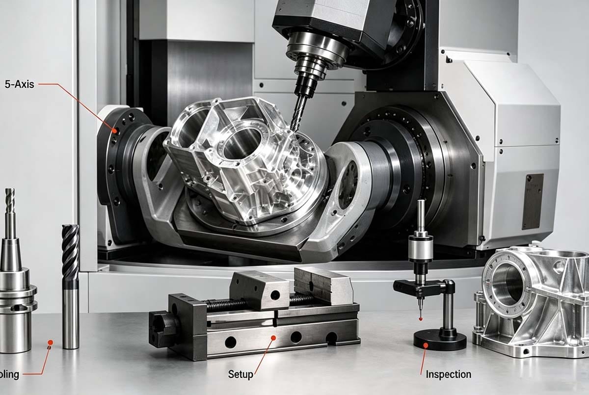
- 5-axis CNC machining of the rotor: The rotor is machined from a solid billet or forging on a 5-axis machining center. Blades are machined using flank milling and point milling strategies. Thin blade sections require special attention to tool deflection, chatter avoidance, and residual stress management.
- Duct machining: The duct ID is turned or bored to achieve the precise diameter and roundness required for the tip clearance gap. Mounting features, strut attachment points, and flange faces are machined in the same setup to ensure concentricity.
- Hub and shaft machining: The hub bore, keyway or spline, and shaft mounting faces are machined with tight concentricity tolerances to the rotor OD.
- Balancing: The assembled rotor (blades + hub) is dynamically balanced. For ducted fans, in-situ balancing with the fan mounted in its bearings and driven by its motor is often performed to account for the assembly”s cumulative unbalance.
- Assembly and clearance verification: The rotor is installed in the duct, and the tip clearance gap is verified at multiple positions around the circumference. Shims or eccentric adjustment mechanisms may be used to center the rotor within the duct.
Performance-Critical Geometric Features
- Blade tip profile: The gap between the blade tip and the duct ID — the tip clearance — is the single most important geometric parameter for ducted fan performance. A tip clearance of 0.5% of the blade span (e.g., 0.5 mm for a 100 mm blade) is considered good. Each 1% increase in tip clearance (as a fraction of blade span) reduces efficiency by approximately 2-3%.
- Blade setting angle: The angular position of each blade relative to the hub. Errors in setting angle cause one blade to operate at a different angle of attack than its neighbors, creating unsteady aerodynamic forces and vibration at the blade-passing frequency.
- Duct inlet lip radius: The radius of the curved inlet lip at the front of the duct strongly influences the fan”s static thrust performance. Flow separation at the inlet lip can reduce static thrust by 30% or more. The lip profile must be smooth and free of machining marks or steps.
- Stator leading edge alignment: Stator vanes downstream of the rotor must be precisely aligned with the swirling flow from the rotor. Misalignment causes separation on the stator vanes and reduced pressure recovery.
Tik Precision provides complete CNC machining of ducted fan components — rotors, ducts, hubs, stators, and support structures — on our 5-axis platforms. From prototype UAV propulsion fans to industrial-scale ducted blowers, we deliver the aerodynamic precision your design requires. Contact us to discuss your ducted fan project.


.jpg)