.jpg)
In precision CNC machining quotes, tolerance requirements are often the single biggest variable driving unit price. Many engineers default to blanket ±0.01mm callouts across a drawing without realizing how much this inflates cost and extends lead time. This article covers tolerance callout logic and GD&T (Geometric Dimensioning and Tolerancing) application to help engineers and buyers communicate more precisely.
1. Tighter Tolerances Don’t Automatically Mean “More Precise”
Standard CNC machining capability (3-axis vertical machining center) typically breaks down as:
- General dimensions: ±0.05mm
- Precision fit dimensions: ±0.02mm
- High-precision fits (requiring grinding or wire EDM): within ±0.005mm
Each order-of-magnitude tightening of tolerance produces a non-linear increase in machining time, inspection cost, and scrap rate. If every dimension on a drawing is called out at ±0.01mm, suppliers will typically quote the entire part at the tightest tolerance level — even when 95% of dimensions don’t actually need that precision.
Practical recommendation: Only apply tight tolerances to dimensions that genuinely affect assembly, sealing, or moving fits. Use a general tolerance standard (ISO 2768 or ASME Y14.5 default tolerance blocks) for everything else, and note it in the title block, e.g., “Unless otherwise specified, tolerances per ISO 2768-m.” This single habit typically saves 10-20% on machining cost.
2. GD&T: A More Precise Language Than Linear Tolerances
Traditional linear (±X) tolerances only constrain deviation in a single direction and struggle to accurately describe geometric relationships. GD&T (per ASME Y14.5 or ISO 1101) uses symbols like position, flatness, perpendicularity, and concentricity to precisely define functional tolerance requirements.
Common GD&T applications in CNC machining:
- Position: Used for hole patterns. Often reflects true assembly feasibility better than an equivalent linear tolerance box, and the allowed tolerance zone is frequently wider than the linear equivalent — actually easing machining difficulty
- Flatness: Critical for sealing surfaces and datum planes
- Concentricity / Runout: Core requirements for shafts and rotating fits
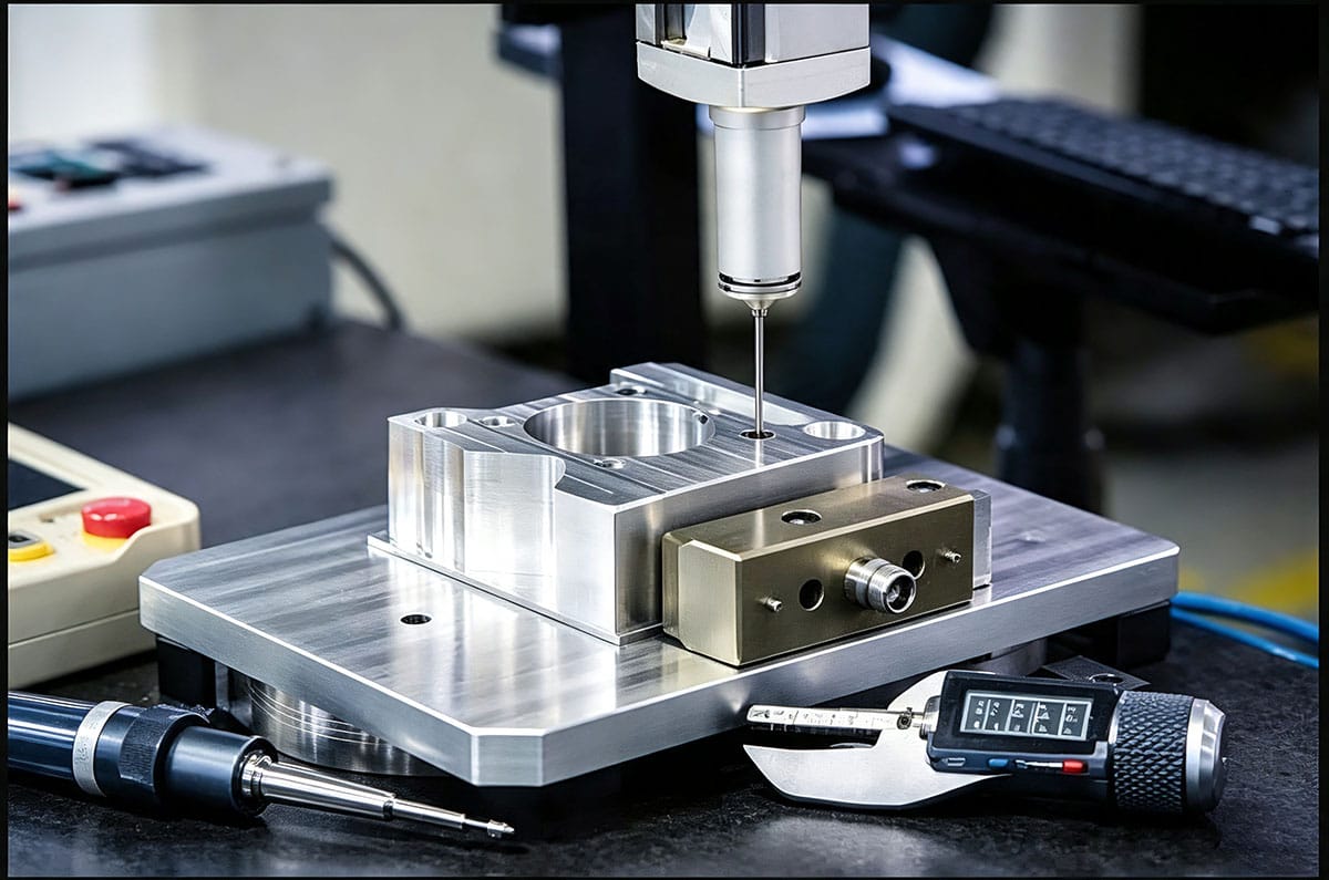
- Datum Reference Frame: Determines fixturing and measurement sequence during inspection, directly influencing CMM programming logic
When discussing quotes, buyers whose drawings use a proper datum reference frame can request inspection reports based on that same datum, avoiding acceptance disputes caused by inconsistent measurement bases.
3. Tolerance Stack-Up: The Hidden Cause of Assembly Failures
A part passing individual tolerance checks doesn’t guarantee assembly success. Tolerances accumulate across an assembly chain (tolerance stack-up). Common analysis methods include:
- Worst Case Analysis: Guarantees 100% interchangeability but forces very tight tolerances on individual parts
- Statistical Tolerancing (RSS, Root Sum Square): Loosens individual part tolerances based on statistical distribution, suitable for high-volume production, but requires stable process capability to support it
For precision assemblies, conduct a tolerance stack-up analysis during the design phase rather than discovering interference after parts are machined.
4. Checklist for Procurement Teams
When reviewing supplier quotes, verify:
- Does the quote distinguish inspection method (full inspection vs. sampling) between “critical dimensions” and “reference dimensions”?
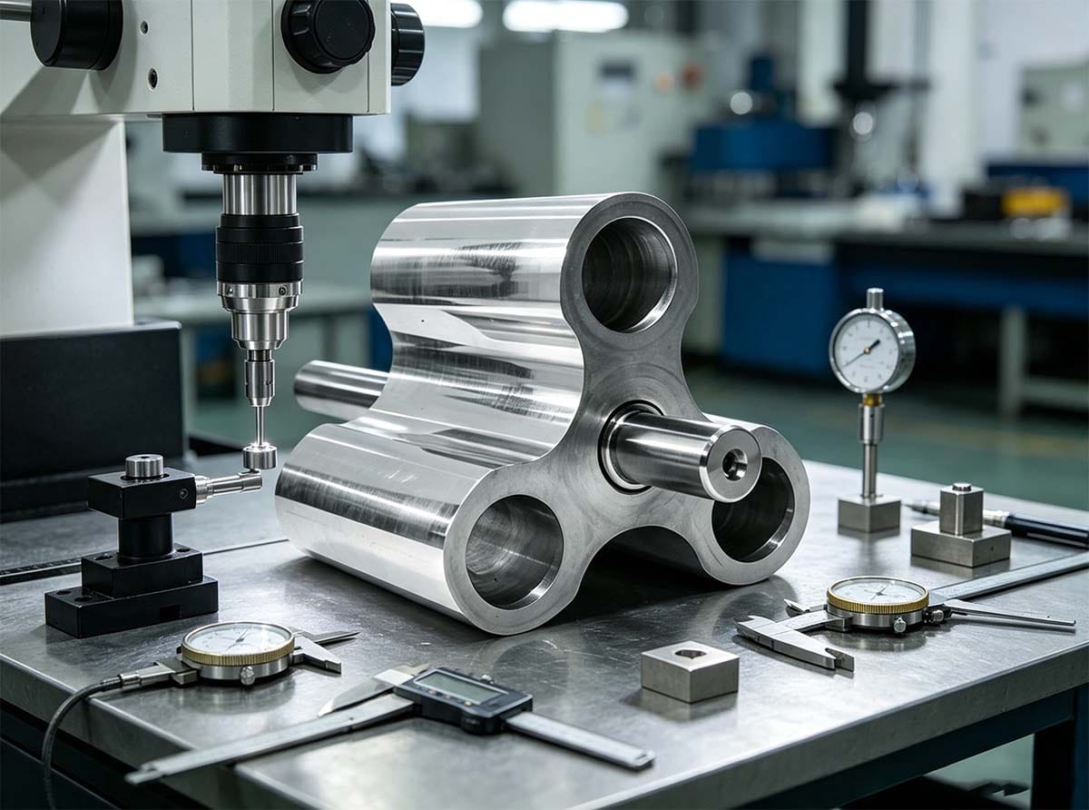
- Does the supplier’s measurement equipment satisfy the 10:1 accuracy rule (gauge resolution should be at least 1/10 of the tolerance)?
- Does the inspection report reference the GD&T datum structure (rather than just a pass/fail list)?
The precision of tolerance callouts fundamentally determines whether engineering intent gets executed correctly by the supplier. A clearly communicated drawing reduces both communication overhead and rework risk far more effectively than repeated email clarifications.