The performance and reliability of any vacuum pump — whether Roots blower, screw, claw, scroll, or turbomolecular — hinges on two interrelated factors: rotor balance and running clearances. These are not independent concerns; they interact in subtle ways that affect vibration, efficiency, wear, and ultimately pump life. This article covers the principles, methods, and best practices for achieving and verifying balance and clearance in precision vacuum pump rotors.
Rotor Balancing Fundamentals
An unbalanced rotor generates a rotating centrifugal force proportional to the unbalance mass, the radius at which it acts, and the square of the rotational speed (F = m·e·ω²). Because the force increases with the square of speed, a vacuum pump rotor that runs smoothly at 1,500 RPM may exhibit destructive vibration at 6,000 RPM if not balanced to an appropriate grade.
Types of Unbalance
- Static unbalance: The rotor”s center of mass is offset from the axis of rotation. The centrifugal force is in a single radial direction. Static unbalance can be corrected by adding or removing mass in a single correction plane — essentially single-plane balancing.
- Couple unbalance: The rotor”s center of mass is on the axis of rotation, but its principal inertia axis is tilted relative to the rotational axis. Two equal and opposite unbalance vectors at opposite ends of the rotor create a rocking couple. Correction requires two planes.
- Dynamic unbalance: The general case — a combination of static and couple unbalance. Most real rotors exhibit dynamic unbalance and require two-plane balancing for correction.
Balance Quality Grades (ISO 21940-11 / ISO 1940)
| Grade | Permissible Eccentricity (µm) at 10,000 RPM | Typical Application |
|---|---|---|
| G6.3 | 6.0 | Industrial Roots blowers, general-purpose vacuum pumps, fans |
| G2.5 | 2.4 | Screw vacuum pumps, claw pumps, high-speed Roots blowers, compressor rotors |
| G1.0 | 0.96 | Precision screw pumps, high-vacuum backing pumps, high-speed motor rotors |
| G0.4 | 0.38 | Turbomolecular pump rotors, ultra-high-speed spindles, gyroscope rotors |
Balancing Methods and Equipment
Balancing Machine Types
- Hard-bearing balancing machines: The bearing supports are stiff relative to the rotor mass. The machine measures the force transmitted to the bearings. Ideal for production environments — calibration is permanent, and the machine can balance a wide range of rotor sizes without recalibration.
- Soft-bearing balancing machines: The bearing supports are flexible, allowing them to move in response to rotor unbalance. The machine measures displacement rather than force. More sensitive than hard-bearing machines for very light rotors or very low unbalance levels, but requires calibration for each rotor type.
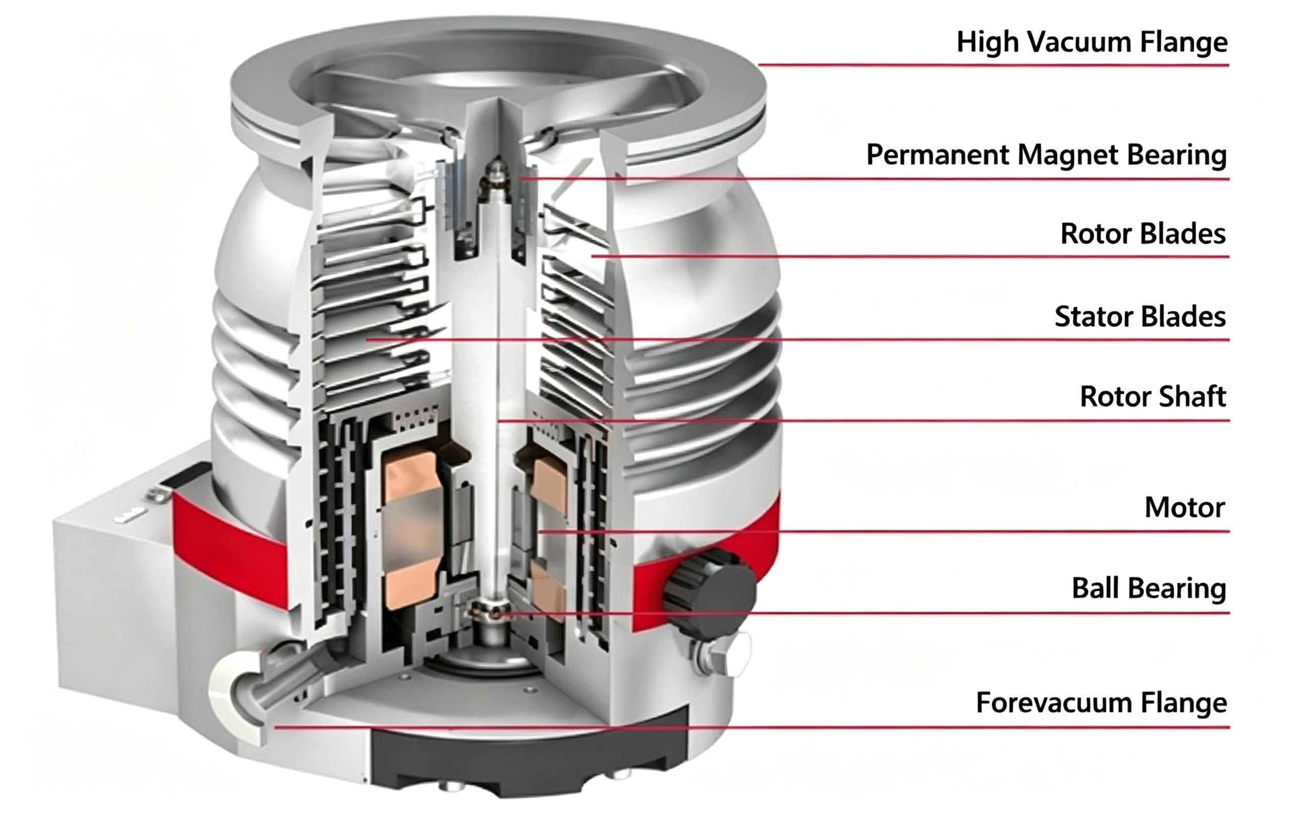
- High-speed balancing machines: Enclosed machines capable of spinning rotors at service speed under vacuum (to eliminate aerodynamic drag). Used for turbomolecular pump rotors and other ultra-high-speed components where the balance state at operating speed may differ from the low-speed balance state due to elastic deformation and thermal effects.
Correction Methods
- Material removal: Drilling, milling, or grinding material from the rotor at calculated angular positions. For cast iron Roots rotors, shallow drill holes in the end faces are the most common method. The removed mass is precisely controlled — each correction is verified on a re-spin.
- Mass addition: Adding balance weights at the correction planes. Screw-on or press-fit weights on accessible surfaces; adhesive-bonded weights for sealed or coated rotors where drilling would compromise surface integrity. Welded-on weights for permanent installations.
- Set-screw or threaded insert adjustment: Tapped holes in the rotor hub accept set screws of varying lengths or mass. Fine balance adjustment is achieved by changing screw length or material (steel vs. brass vs. nylon). Used for rotors that require field balancing capability.
- Laser material removal: For turbomolecular pump rotors and other high-value, high-speed rotors, laser ablation provides non-contact, high-precision mass removal with sub-milligram resolution. No cutting forces, no tool wear, and the process can be automated.
Clearance Control Strategies
Running clearances in vacuum pumps serve a dual purpose: they must be large enough to prevent rotor-to-housing or rotor-to-rotor contact under all operating conditions, but small enough to minimize gas leakage (backflow) that reduces volumetric efficiency. Managing these clearances is a central challenge in vacuum pump engineering and manufacturing.
Clearance Types
- Radial clearance: The gap between the rotor OD and the housing bore. Determined by the rotor OD tolerance and housing bore tolerance, plus allowances for thermal expansion, bearing clearance, and shaft deflection under load.
- Inter-rotor clearance: The running gap between mating rotors (e.g., Roots rotor lobes, screw rotor flanks). Governed by profile accuracy and timing gear precision.
- Axial (end) clearance: The gap between rotor end faces and the housing end plates or bearing plates. Determined by rotor length tolerance, housing depth tolerance, and thermal expansion allowance.
Factors Affecting Running Clearance
| Factor | Effect | Mitigation |
|---|---|---|
| Thermal expansion | Rotor and housing expand at different rates. Aluminum rotors in cast iron housings can close clearances by 0.1-0.3 mm at operating temperature. | Calculate thermal growth and increase cold clearance accordingly. Use materials with matched thermal expansion coefficients where possible. |
| Shaft deflection | Bending under gas pressure loads and rotor weight moves the rotor toward the housing bore. Worst-case at the rotor mid-span. | Stiff shaft design. Increase bearing span. Use steady bearings for long rotors. |
| Bearing internal clearance | Angular contact bearings have inherent axial and radial clearance that allows the rotor to shift position. | Preloaded bearing arrangements (back-to-back or face-to-face duplex pairs) eliminate internal clearance. |
| Housing bore ovality | Out-of-round housing bores cause non-uniform radial clearance. At the minimum-clearance direction, the rotor may contact the housing. | Specify and inspect housing bore roundness. Honing after assembly machining for critical applications. |
| Rotor profile error | Profile deviations create localized tight spots where clearance is less than nominal. | Specify profile tolerance. CMM verification at multiple cross-sections. |
Clearance Measurement Techniques
- Feeler gauge: The traditional method. With the pump partially assembled, a feeler gauge of known thickness is inserted between the rotor and housing at accessible locations. Simple but limited to external clearances.
- Plastigauge: A crushable plastic strip placed on the rotor surface before closing the housing. After disassembly, the crushed width indicates the minimum clearance. Provides a direct measurement of the actual assembled clearance.
- Lead wire: Soft lead wire placed between assembled components. The crushed thickness indicates clearance. Used for larger clearances (>0.1 mm) where Plastigauge may not be accurate.
- Dial indicator sweep: The rotor is rotated by hand while a dial indicator measures the gap between the rotor and housing at multiple positions. Provides a clearance map around the full circumference.
- CMM-based clearance prediction: The machined rotor is measured on the CMM; the machined housing is measured on the CMM. The two datasets are virtually assembled in software to predict the running clearance at all positions. No physical assembly required; used for first-article verification and supplier qualification.
Integrated Approach: Balance and Clearance Together
Balance and clearance are not independent problems. A rotor with poor balance will vibrate, and that vibration amplitude may exceed the running clearance even though the static clearance is adequate. Conversely, a rotor with excessive clearance may run smoothly from a vibration standpoint but suffer from poor volumetric efficiency due to excessive gas backflow.
The engineering approach is iterative:
- Design the rotor and housing for the target clearance at operating temperature
- Specify manufacturing tolerances that achieve that clearance with adequate process capability (Cpk ≥ 1.33)
- Balance the rotor to the grade appropriate for its operating speed
- Verify clearance and balance on the first article
- Monitor both parameters in production using SPC methods
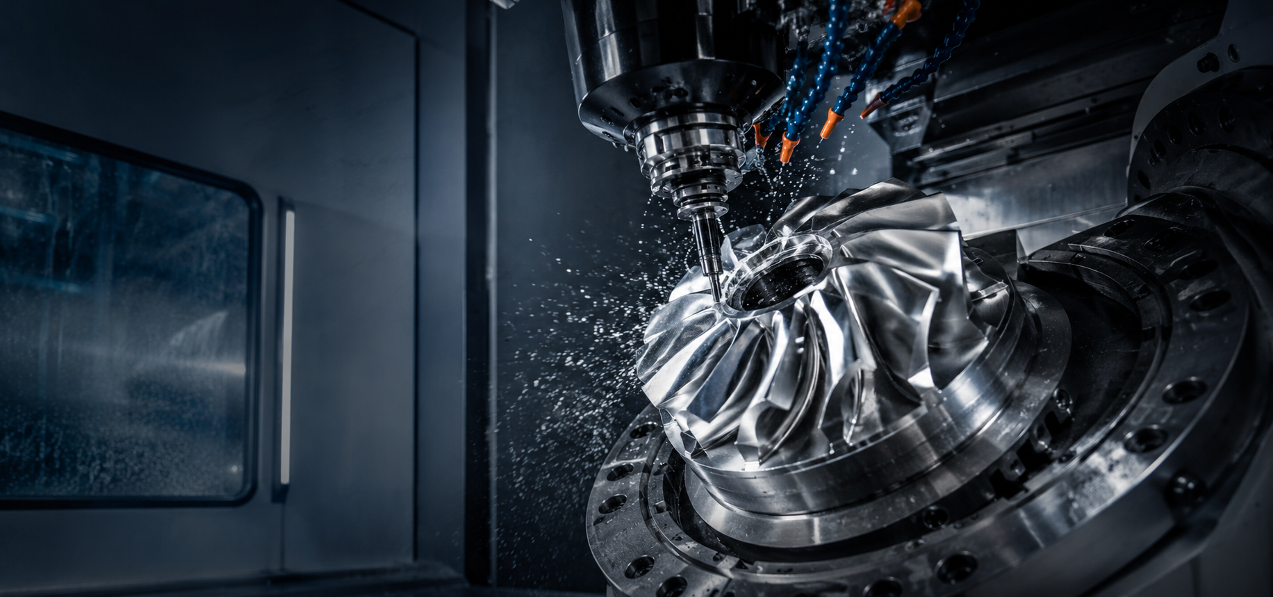
Tik Precision provides complete rotor manufacturing — from 5-axis CNC machining through dynamic balancing and clearance verification. Our integrated approach ensures that the rotors you receive are balanced and dimensionally correct, ready for assembly. Contact us to discuss your vacuum pump rotor requirements.