Wind turbine main shaft machining is a critical manufacturing process. The main shaft transfers rotor energy to the gearbox or generator. It must withstand torque, bending loads, vibration, and changing wind conditions throughout its service life.
Reliable production requires more than precision machining. Forging, heat treatment, deep-hole machining, inspection, and documentation must work together. This guide explains the manufacturing process, key quality controls, and common inspection methods.
What Is a Wind Turbine Main Shaft?
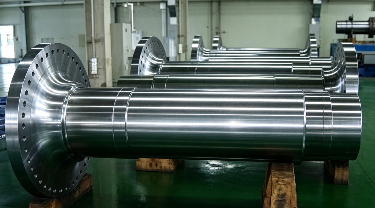
A wind turbine main shaft is a large, load-bearing drivetrain component. It connects the rotor hub to the gearbox or generator. Its design and material depend on the turbine capacity, load requirements, and connection method.
Most main shafts have the following characteristics:
- Large size: Utility-scale shafts can be several metres long and weigh more than ten tonnes.
- Flange connections: Flanges and bearing seats require accurate dimensions and tight geometric tolerances.
- Alloy-steel construction: Large alloy-steel forgings provide the strength and toughness needed for heavy loads.
Wind Turbine Main Shaft Manufacturing Process
1. Material preparation and forging
The process begins with approved alloy steel and material certificates. The manufacturer selects open-die forging or die forging according to the shaft design and production volume. Controlled forging improves the internal grain flow and helps achieve consistent mechanical properties.
2. Rough machining
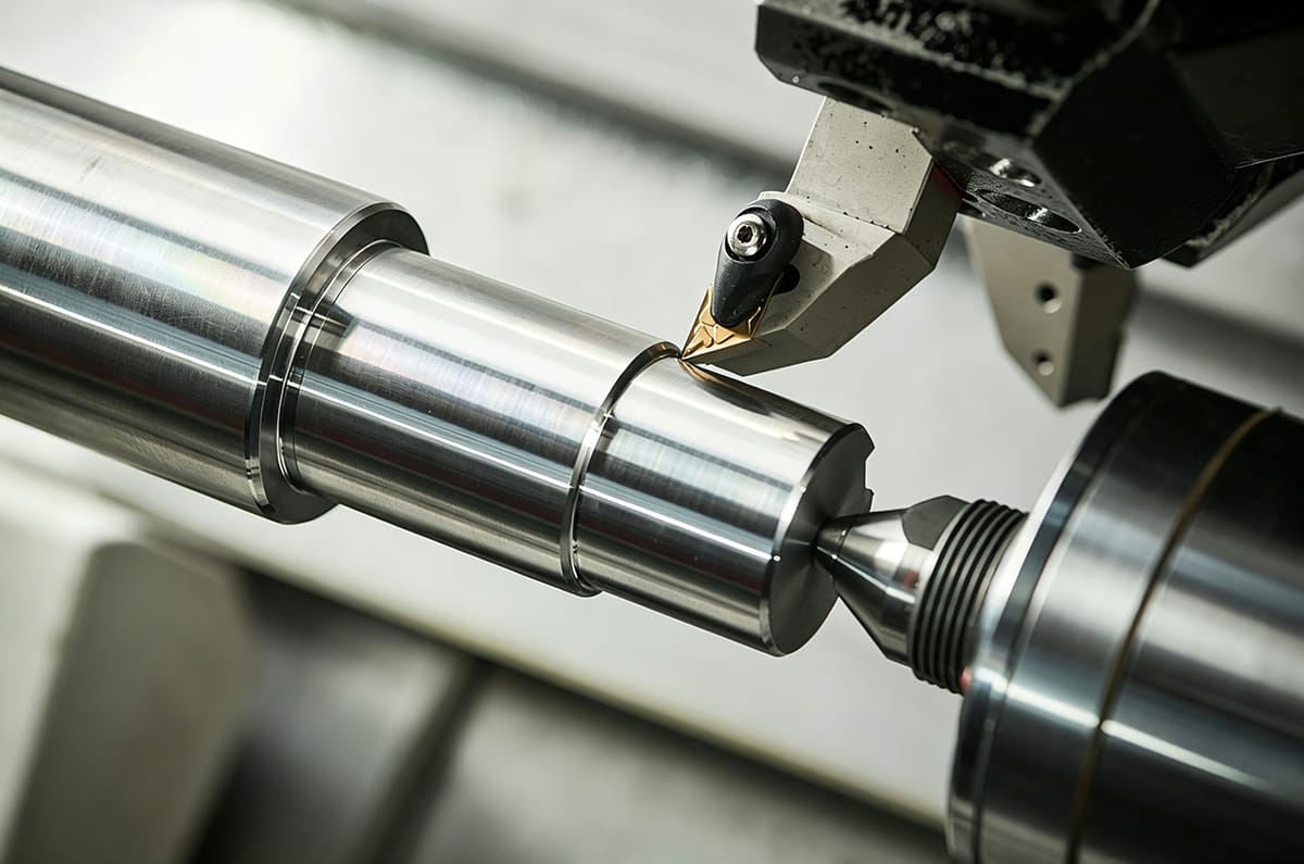
Rough turning removes scale and excess material from the forging. It also establishes the datum references used during later machining operations.
3. Heat treatment
Quenching and tempering provide the required balance of strength and toughness. The heat-treatment process must be recorded and controlled because large forgings can deform or develop residual stress during cooling.
4. Semi-finishing and deep-hole machining
Some main shafts include a central bore for cables or other equipment. Deep-hole drilling or boring may be required. The process must control bore diameter, straightness, chip removal, and internal surface quality.
5. Finish machining
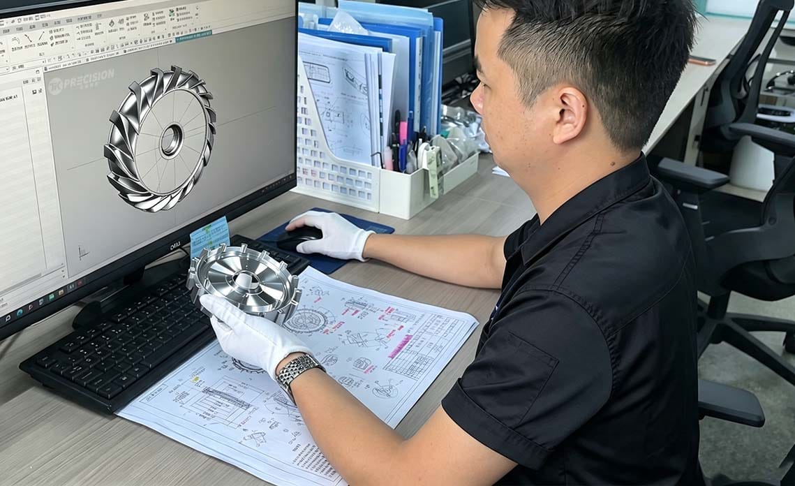
Finish turning and grinding produce the final dimensions of bearing seats, flange faces, and other assembly interfaces. These functional surfaces may require strict control of roundness, cylindricity, concentricity, runout, and surface roughness. For complex rotating components, manufacturers may also use 5-axis CNC machining to reduce setup errors and improve positional accuracy.
6. Non-destructive testing
Ultrasonic testing can identify internal discontinuities. Magnetic particle testing can detect surface and near-surface indications. The inspection method and acceptance criteria should follow the drawing, project specification, and approved quality plan. For more information, see this guide to CNC machining inspection failures and prevention.
Critical Quality Controls
Several controls have a direct effect on wind turbine main shaft reliability:
- Deformation control: Inspect the shaft after heat treatment and perform approved straightening when necessary.
- Bearing-seat accuracy: Check diameter, roundness, cylindricity, and surface roughness because these features affect bearing life.
- Deep-hole accuracy: Control bore size, straightness, alignment, and internal finish throughout the operation.
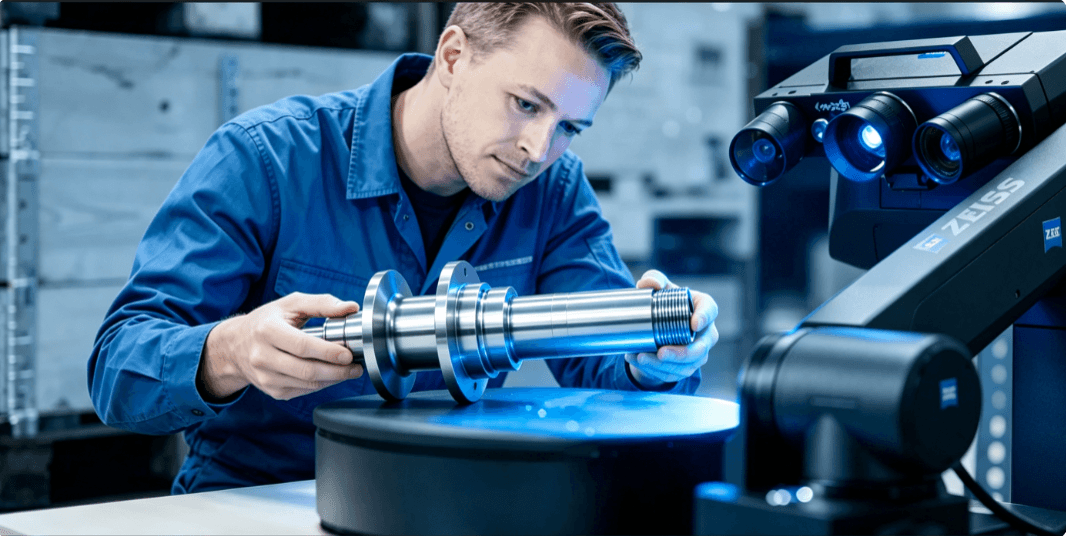
- Large-part measurement: Use suitable fixtures, large measuring systems, laser trackers, or other approved equipment.
- Process stability: Monitor tools, cutting parameters, workholding, temperature, and measurement references to reduce variation.
Inspection Methods for Main Shafts
The inspection plan should be based on the material grade, drawing, shaft geometry, applicable specifications, and functional requirements. Typical checks include:
- Dimensional inspection of diameters, lengths, flanges, and bearing seats
- Roundness, cylindricity, concentricity, and runout measurement
- Surface roughness measurement on functional interfaces
- Ultrasonic testing for internal discontinuities
- Magnetic particle testing for surface indications
- Mechanical-property and material-certificate verification
- Final visual inspection and documentation review
Documentation and Traceability
Each main shaft should have a documented quality record. The record may include material certificates, chemical analysis, mechanical-test results, forging records, heat-treatment charts, non-destructive testing results, dimensional reports, and final inspection records.
Traceability links these records to the individual component. It also helps manufacturers investigate non-conformances, complete corrective actions, and meet customer or project requirements.
How to Improve Manufacturing Reliability
Manufacturers can improve reliability by reviewing critical dimensions before production, defining datum references clearly, planning for heat-treatment deformation, inspecting the first completed part, and monitoring process trends throughout the batch.
The best results come from coordinating forging, heat treatment, machining, inspection, and documentation. Optimising only one operation may not provide consistent final performance.
Conclusion
Wind turbine main shaft machining combines large-scale forging, controlled heat treatment, precision machining, and advanced inspection. A complete process plan improves dimensional consistency, traceability, and long-term drivetrain reliability.
For a project-specific manufacturing review, provide the shaft drawing, material grade, heat-treatment requirements, critical tolerances, inspection standard, expected quantity, and required documentation.