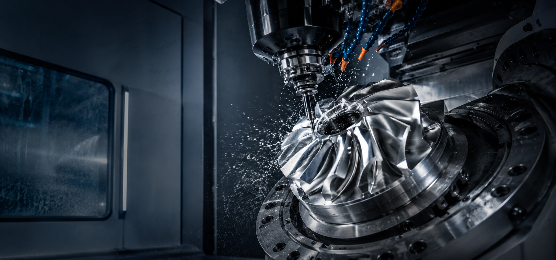
The difference between a mediocre impeller and a precision one often has less to do with the machine tool and more to do with the digital preparation — the CAD model quality and the CAM programming strategy. For impellers, where toolpaths must navigate deeply curved, tightly spaced surfaces with zero room for error, the programmer”s skill is amplified. This article explores the CAD/CAM workflow that produces aerospace-grade impellers on 5-axis CNC machines.
CAD Modeling for Impellers: Getting the Foundation Right
The impeller manufacturing process begins with a 3D CAD model — and that model must be more than just geometrically accurate. It must be constructed in a way that CAM software can interpret correctly.
Native Geometry vs. Imported Surfaces
Ideally, the CAD model should be created in a system that natively supports NURBS surface modeling — Siemens NX, CATIA, or SolidWorks with advanced surfacing. Impeller blade surfaces imported as STL meshes or poorly translated STEP files can have gaps, overlaps, or inconsistent surface normals that cause CAM toolpath generation to fail or produce gouged surfaces.
Key CAD Requirements for CAM-Ready Impeller Models
- Watertight solid body: The impeller must be a single, closed solid (or a well-defined set of surfaces that form a closed volume). Gaps between the blades and hub, or between the blades and shroud, will cause toolpath generation failures.
- Clean blade surfaces: Each blade face (pressure side, suction side) should be a single, smooth surface — not a patchwork of smaller surfaces stitched together. Stitched surfaces create discontinuities that translate into visible tool marks on the finished part.
- Properly defined leading and trailing edges: The transition from blade to edge radius must be smooth and continuous. Sharp mathematical edges are impossible to machine and cause CAM algorithms to fail.
- Hub surface as a single swept or revolved surface: The hub floor should be continuous from blade root to blade root, with no seams or patch boundaries.
- Accurate fillets and blends: The blade-to-hub and blade-to-shroud fillet radii must be explicitly modeled — they determine the minimum tool radius required and the achievable surface finish in these critical stress-concentration zones.
CAM Programming: The Art and Science of Impeller Toolpaths
With a clean CAD model, CAM programming begins. Modern CAM software — HyperMill, NX CAM, Mastercam with Blade Expert, Esprit, and others — provides impeller-specific modules that dramatically reduce programming time compared to general-purpose 5-axis toolpath strategies.
The Programming Sequence
Step 1: Define the Machining Coordinate System
The impeller is typically oriented with its axis of rotation aligned to the machine”s rotary axis (A-axis for trunnion-style machines, C-axis for rotary-table machines). The coordinate system origin is placed at the center of the bore on the hub face, establishing the reference for all subsequent operations.
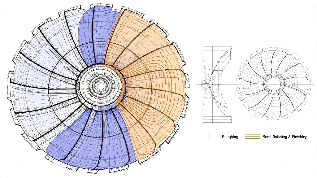
Step 2: Roughing — Bulk Material Removal
Roughing removes 80-90% of material between the blades. Two primary strategies:
- Plunge roughing: A large-diameter tool plunges axially between blades, removing material in stepped increments. Fast and effective for deep inter-blade cavities but leaves significant scallops that semi-finishing must address.
- Trochoidal roughing: The tool follows a circular or spiral path with a small radial engagement, maintaining constant chip load. Generates less heat, reduces tool wear, and leaves a more uniform stock allowance for semi-finishing. Preferred for tough materials like titanium and stainless steel.
Step 3: Semi-Finishing — Establishing the Profile
Semi-finishing removes the uneven stock left by roughing and establishes a uniform material allowance — typically 0.1-0.3 mm — for the finishing pass.
- Morph toolpaths: The toolpath smoothly transitions between two boundary curves (e.g., blade profile curves at the hub and at the shroud). Maintains constant stepover across the variable-width blade surface.
- Hub floor semi-finishing: A bull-nose end mill follows the hub curvature, removing roughing scallops and preparing the surface for hub finishing.
Step 4: Finishing — Achieving the Final Surface
This is where impeller quality is determined. The finishing toolpaths must maintain precise tool orientation relative to the surface at every point.
- Flowline finishing: The tool follows isoparametric curves (the natural “grain” of the NURBS surface). Produces the best surface finish because the tool direction aligns with the fluid flow path.
- Multi-blade finishing: The CAM software automatically transitions between adjacent blades, machining the pressure side of one blade and the suction side of the next in a single continuous motion, minimizing air-cutting time.
- Point milling vs. flank milling: Point milling uses the tip of a ball end mill and produces a cusp height determined by stepover distance. Flank (swarf) milling uses the side of the tool and can produce a smoother finish with fewer passes — but requires ruled surfaces (surfaces that can be generated by a straight line moving along a path). Most impeller blades are not ruled surfaces and require point milling.
Step 5: Edge Profiling and Deburring
The leading and trailing edges of impeller blades are machined to a precise radius — typically 0.1-0.5 mm. A dedicated toolpath profiles each edge, blending into the blade and hub surfaces. Remaining sharp corners at the blade tips and hub transitions are deburred — either by programmed chamfer toolpaths or, for critical edges, by hand under magnification.
Toolpath Verification: Simulation Before Execution
Impeller toolpaths are too complex to trust without verification. Modern CAM software includes machine simulation that models the entire CNC machine — including the spindle, tool holder, fixture, and workpiece — and simulates the complete machining sequence. The simulation detects:
- Collisions between the tool holder and the workpiece or fixture
- Gouges where the tool removes material beyond the intended surface
- Excess material left by insufficient toolpath coverage
- Axis over-travel where the machine”s physical limits are exceeded
For closed impellers, collision detection is particularly critical — the limited access through the inlet eye means the tool holder and spindle nose are constantly at risk of contacting the shroud.
Optimizing for Cycle Time
Impeller machining cycle time is often measured in shifts, not hours. Optimization strategies include:
- Adaptive clearing: The CAM software adjusts tool engagement in real-time, maintaining constant chip load and enabling higher feed rates.
- Optimized tool changes: Group all operations using the same tool to minimize tool change time.
- Directional finishing: Machining from the blade tip toward the hub (or vice versa) affects surface finish and tool deflection. The programmer selects the direction that minimizes deflection and maximizes finish quality.
- Toolpath smoothing: Excessive small linear moves in a toolpath create data starvation at the CNC controller, forcing the machine to slow down. Modern CAM software applies toolpath smoothing (arc fitting, spline interpolation) to produce continuous, smooth motion at high feed rates.
Tik Precision”s CAM engineers specialize in complex 5-axis impeller programming. We use industry-leading software and verification tools to ensure that every impeller we machine meets specifications on the first attempt. Upload your CAD files for a programming review and quote.