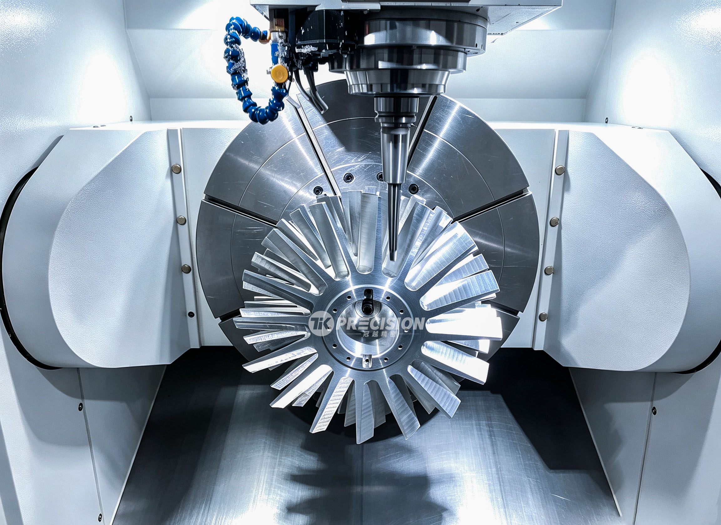
Master the complexities of 5‑axis impeller machining – from material selection and CAM programming to inspection and real‑world applications.
What Is an Impeller and Why Does Machining It Matter?
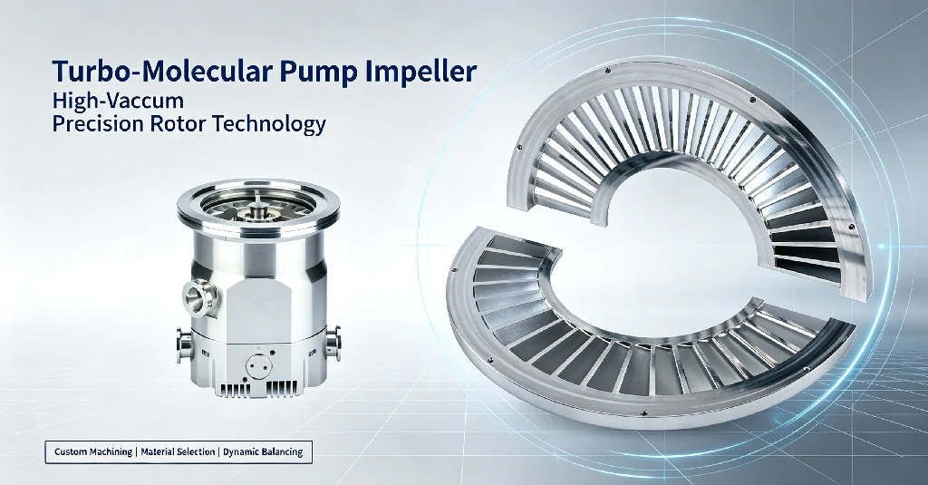
An impeller is a rotating disk with curved blades that moves or compresses fluids (gases or liquids) in pumps, compressors, turbochargers, and jet engines. Its blade geometry directly determines efficiency, pressure ratio, and fuel consumption – which is why even microscopic deviations in profile can degrade performance by 5‑10% in critical applications.
Unlike simple shafts or housings, impellers are freeform surfaces with twisted, tapered blades and narrow flow channels. Manufacturing them isn’t just “cutting metal” – it’s a high‑stakes interplay of geometry, materials, and machine dynamics.
Why Impeller Machining Is One of the Toughest CNC Challenges
1. Blade Geometry – A 3D Puzzle
Blades have variable thickness (thick at the hub, thin at the tip)
Multiple twist angles along the blade height
Narrow gaps between blades (sometimes < 3 mm) that limit tool access
The risk: With 3‑axis machining, you need multiple setups, each introducing alignment errors. The result? Mismatched blade profiles, vibration, and early fatigue failure.
2. Micron‑Level Tolerances
High‑speed compressors spin at 50,000+ RPM – a 0.01 mm imbalance can cause destructive vibration. Typical requirements:
| Parameter | Typical Value |
|---|---|
| Dimensional accuracy | ±0.005 mm (5 microns) |
| Surface finish | Ra 0.8 – 1.6 μm (mirror‑like for flow efficiency) |
| Runout (balance) | ≤ 2 μm |
| Inspection method | CMM + non‑contact optical scanning |
3. The “Unmachinable” Materials
Aluminum 7075 – easy to cut, but prone to built‑up edge
Titanium Ti‑6Al‑4V – high strength, low thermal conductivity (heat stays in the tool)
Inconel 718 – work‑hardens immediately, extreme tool wear (up to 10× faster than steel)
Each material demands different cutting speeds, feeds, coatings, and coolants – a one‑size‑fits‑all approach guarantees scrap.
The Game‑Changer: 5‑Axis Simultaneous CNC Machining
Why 5‑axis? Because it tilts and rotates the tool while cutting, maintaining an optimal engagement angle with the blade surface. This delivers:
Single‑setup completion – machine the hub, both blade faces, and flow channels without repositioning
Better surface finish – constant tool contact reduces scallop height (down to Ra 0.8)
Shorter cycle times – up to 40% faster than 3+2 axis indexing, because you avoid retract/approach moves
Real‑world example: A centrifugal compressor impeller (diameter 200 mm, 12 blades) that took 8 hours on a 3‑axis machine can be finished in under 3 hours on a modern 5‑axis mill – with 50% fewer scrap parts.
Step‑by‑Step: The Impeller Manufacturing Workflow
Step 1 – CAD Model & Feasibility Review
Engineers check for:
Draft angles – do blades have enough taper for tool clearance?
Minimum channel width – can a standard end mill (e.g., Ø6 mm) reach the bottom?
Material stock – forging, casting, or near‑net shape? (forging is preferred for grain flow integrity)
Step 2 – Design for Manufacturing (DFM) Optimization
We often suggest minor geometry tweaks – e.g., adding a fillet radius at the blade‑hub junction – that dramatically reduce stress concentration without affecting aerodynamics. This step alone can cut machining time by 20%.
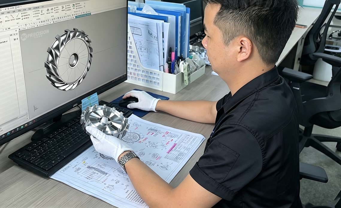
Step 3 – CAM Programming with Collision Avoidance
Modern CAM (like HyperMILL or NX) uses tool‑axis smoothing and automatic collision checking against the fixture and adjacent blades. Programmers define:
Roughing strategy (high‑feed milling with barrel tools)
Semi‑finishing (constant stepover)
Finishing (ball‑nose or toroidal tools, often with trochoidal paths to avoid sudden load changes)
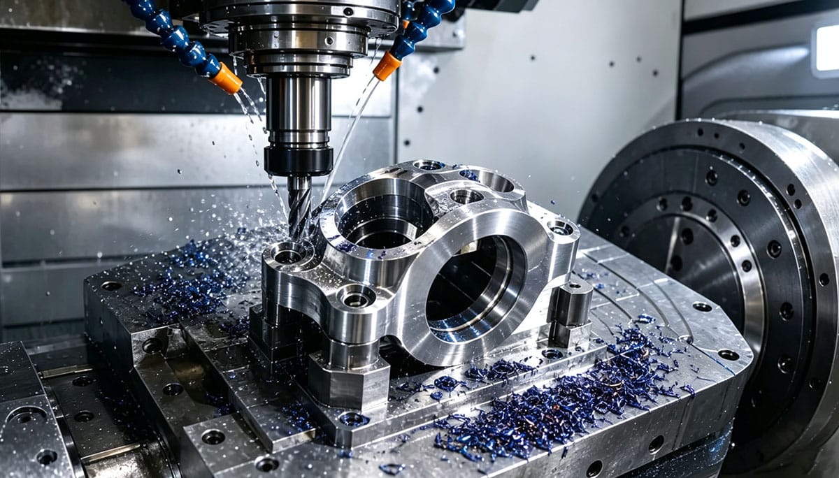
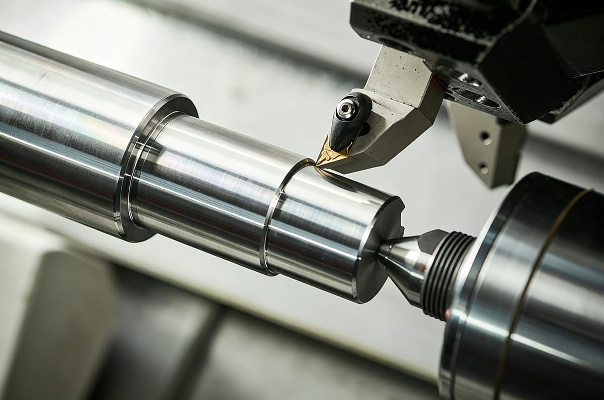
Step 4 – 5‑Axis Machining (Rough → Semi‑Finish → Finish)
Roughing – remove 70‑80% of stock using large‑diameter indexable tools
Semi‑finishing – leave 0.2‑0.3 mm stock, correct for tool deflection
Finishing – use small‑diameter (Ø4‑10 mm) solid carbide tools with AlTiN or diamond coatings; run at high spindle speeds (up to 30,000 RPM) with through‑spindle coolant
Step 5 – Secondary Finishing (Deburring & Polishing)
Manual or robotic deburring removes sharp edges that create turbulence. For ultra‑smooth flow, we apply abrasive flow machining (AFM) – a putty‑like abrasive media pushed through the channels under pressure.
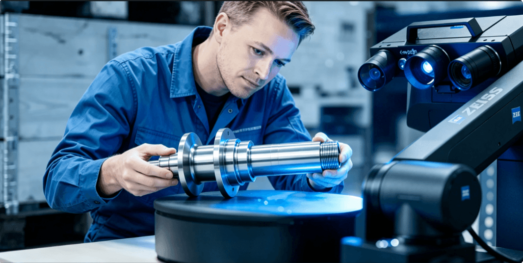
Step 6 – Inspection & Documentation
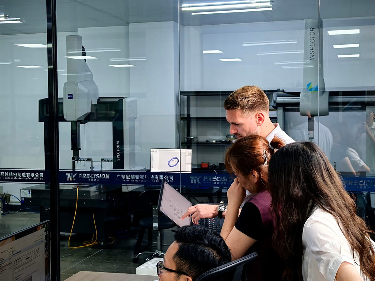
CMM – measures blade profiles against the CAD nominal (deviation ≤ ±5 μm)
Surface roughness – portable profilometer checks Ra values
Balance – dynamic balancing to ISO 1940 G2.5 or better
Material certs – tensile, hardness, and grain size verification
Materials Deep‑Dive: Which One Fits Your Application?
| Material | Best For | Machining Tips | Cost Factor |
|---|---|---|---|
| Aluminum (6061, 7075, A356) | Turbocharger wheels, low‑temp compressors | Use polished carbide tools, high feed, avoid built‑up edge with MQL | ★★☆ |
| Titanium (Grade 5, 6Al‑4V) | Aerospace engine fans, cryogenic pumps | Low cutting speed (30‑50 m/min), high feed per tooth, abundant coolant, use ceramic or PCD tools | ★★★★ |
| Inconel 718 / Waspaloy | Turbine exhaust, high‑temp (700°C+) gas compressors | Constant chip load, avoid dwell, use coated carbide with TiAlN, rigid setup – deflection is the enemy | ★★★★★ |
| Stainless Steel (17‑4PH, 316L) | Industrial pumps, marine applications | Moderate speed, use chip‑breaker geometry, maintain positive rake | ★★★ |
Pro tip: For prototype runs, aluminium is 5‑10× cheaper and faster to machine – perfect for validating aerodynamic design before committing to expensive Inconel.
Common Defects & How to Avoid Them (Practical Lessons)
| Defect | Root Cause | Prevention |
|---|---|---|
| Blade thinning at tip | Tool deflection | Use short, rigid tool holders; reduce radial depth of cut; consider tapered shank tools |
| Surface chatter marks | Low spindle rigidity or unsuitable feed | Increase spindle speed, reduce feed per tooth, use variable‑pitch end mills |
| Burr formation on trailing edge | Wrong exit strategy | Program a roll‑off exit or use a deburring pass with a small radius tool |
| Profile deviation > tolerance | Thermal expansion or fixture loosening | Use in‑process probing to compensate; implement coolant temperature control (±1°C) |
Quality Assurance – What a Reliable Supplier Should Provide
When outsourcing impeller machining, demand:
✅ Full CMM report with colour‑coded deviation maps
✅ Balancing certificate (show residual unbalance in g·mm)
✅ First‑article inspection (FAI) per AS9102 or PPAP
✅ Process capability data (Cpk ≥ 1.33 for critical dimensions)
✅ Tool wear logs – consistent tool changes prevent unexpected deviations
We also recommend non‑destructive testing (penetrant or X‑ray) for safety‑critical aerospace impellers.
Applications – Where CNC‑Machined Impellers Are Used
Aerospace – auxiliary power units (APU), cabin air compressors, fuel pumps
Automotive – turbochargers (both gasoline and diesel), superchargers, electric vehicle heat pumps
Oil & Gas – pipeline compressors, flare gas recovery, subsea multiphase pumps
Medical – ventilators, surgical suction pumps (small, high‑precision impellers)
Energy – hydrogen recirculation blowers, organic Rankine cycle turbines
Frequently Asked Questions (From Our Engineers)
Q: Can you machine an impeller from a 3‑axis mill?
A: Yes, but only for simple, low‑performance designs. For twisted blades with tight channels, 5‑axis is mandatory – otherwise you’ll need multiple setups and hand‑finishing, which kills accuracy and repeatability.
Q: What’s the largest impeller you can 5‑axis machine?
A: With our large‑frame machines, we handle diameters up to 800 mm and weight up to 500 kg. For micro‑impellers (<50 mm), we use high‑speed spindles (60,000 RPM) with ultra‑small tools.
Q: How do you price impeller machining?
A: Cost depends on material, complexity (blade count, twist), batch size, and required finish. Prototype (1‑5 pcs) is higher per part; production (50+ pcs) benefits from fixturing and CAM reuse. We provide a free DFM review with a firm quote.
Q: What lead time should I expect?
A: Programming takes 1‑3 days for a typical impeller. Machining runs from 2 hours (small aluminium) to 20 hours (large Inconel). Total lead time – including inspection – ranges from 5 to 15 working days.
Q: Do you offer post‑machining treatments?
A: Yes – heat treatment (stress relief, ageing), anodising (for aluminium), passivation (for stainless), and specialised coatings (DLC, TiN) for wear resistance.
Choosing the Right Manufacturing Partner – 5 Red Flags to Avoid
“We don’t do simulation” – without tool‑path simulation, collisions are almost guaranteed.
“Our standard tolerance is ±0.02 mm” – that’s 4× looser than impellers need.
“We use the same tool for aluminium and Inconel” – immediate sign of poor process knowledge.
“Inspection? Just a go/no‑go gauge” – insufficient for freeform profiles.
“No DFM feedback” – if they don’t suggest improvements, they’re not adding value.
Why TikPrecision Stands Out
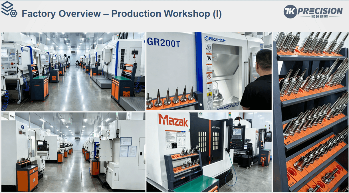
Dedicated impeller cell – we have 5‑axis machines (Hermle, DMG MORI) optimised solely for impeller/blisk work, with vibration‑damping bases and thermal stabilisation.
In‑house CAM experts – our programmers average 12 years of turbomachinery experience; we write custom macros for repetitive features.
Total traceability – every tool, fixture, and inspection step is logged; you get a digital twin of your actual machined part.
Scalable – from 1‑off R&D prototypes to 1,000‑piece production runs with consistent quality.
Ready to Move Forward?
Stop guessing – let’s evaluate your impeller project together.
Upload your CAD model (STEP or IGES) and material specification. Our engineering team will:
Assess manufacturability within 24 hours
Suggest cost‑saving design tweaks (if any)
Provide a fixed price and delivery date – no surprises
[Request Your Free DFM Review & Quote] – click to start.