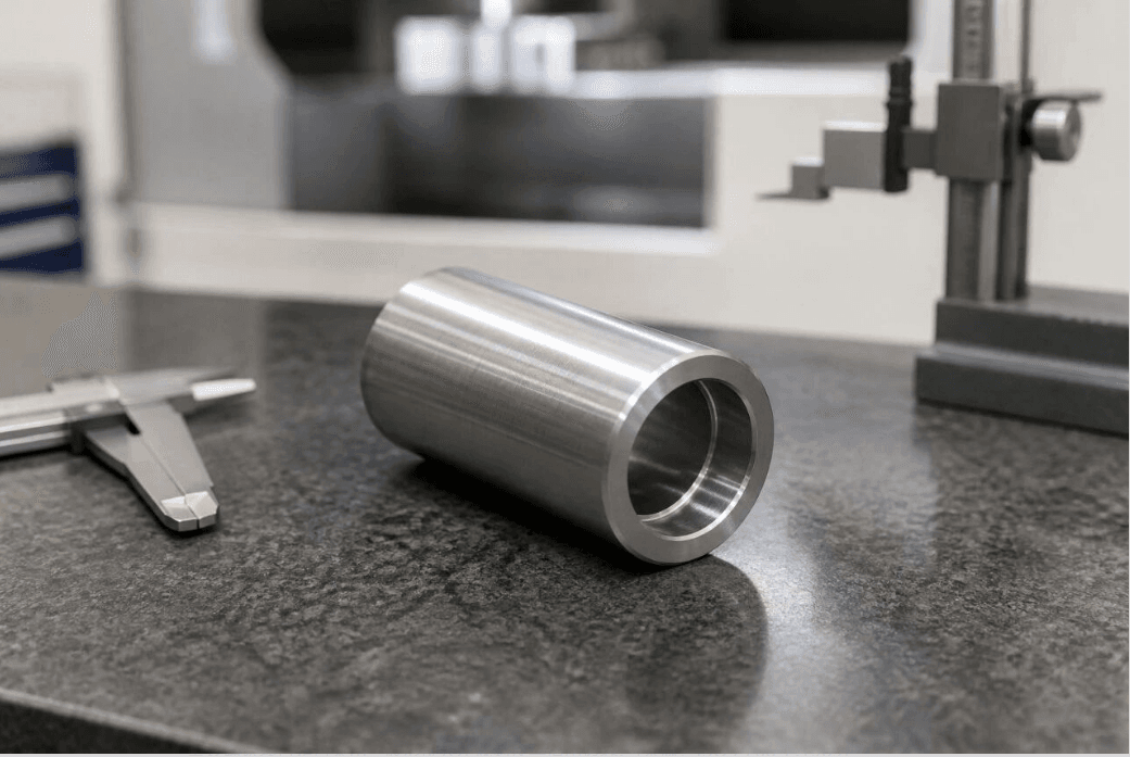
A shaft sleeve cylindrical part can look deceptively simple on the drawing. But sound machining judgment can never stop at “can this be turned on a lathe?” The outer diameter, end faces, axial bore, and stepped bore of a component like this are often functionally interdependent. If datums, fixturing strategy, and inspection logic are not aligned before production begins, every individual dimension can pass inspection in isolation — and the part can still fail to assemble correctly or fail to rotate as intended.
This review discusses only the structural clues that can be safely identified from the engineering drawing itself. Specific dimensions, tolerances, materials, threads, and surface treatments cannot be confirmed from a drawing summary alone, and none of them should be assumed. They must be verified against the controlled drawing and the actual project requirements.
What the Drawing Summary Actually Shows
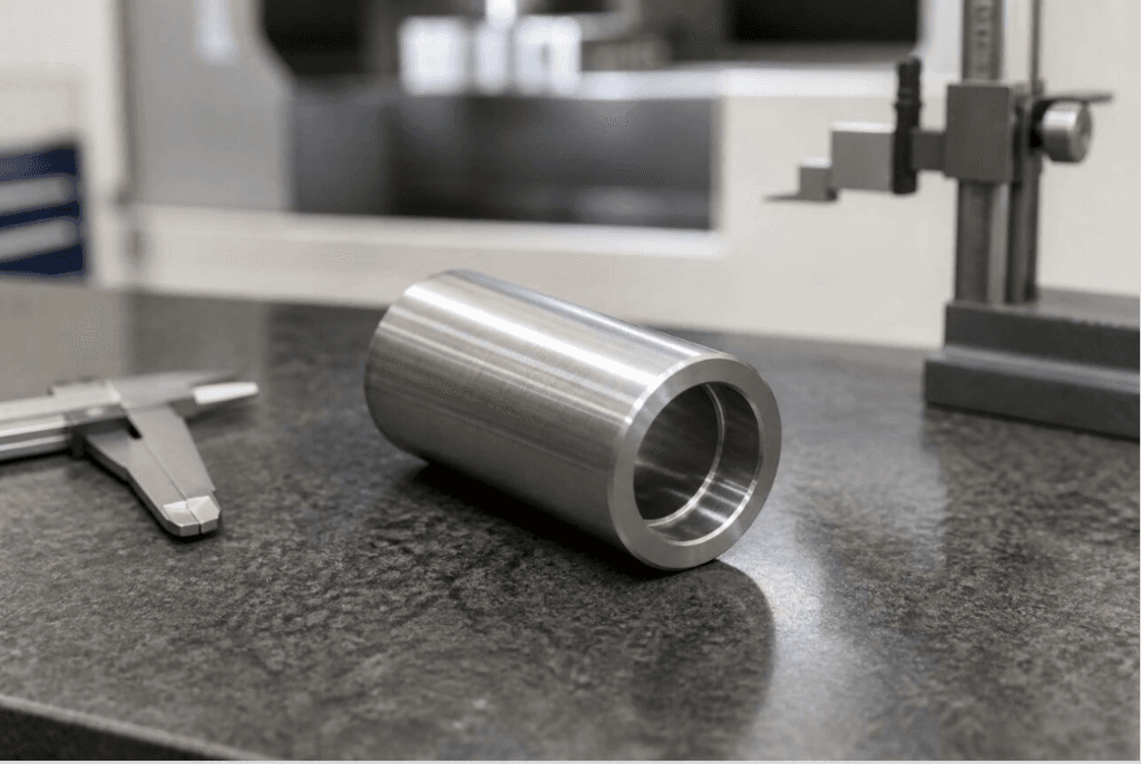
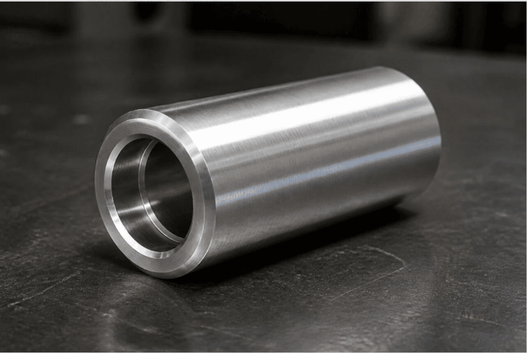
Based on the visible annotations in the customer-supplied engineering drawing, the part can be identified as a shaft sleeve cylindrical component with a cylindrical body, and an axial bore and stepped bore are visible. [Source: visible annotations in customer-supplied engineering drawing] The drawing set includes an end view, a side view, and an isometric view. The outer diameter and axial bore can be reviewed as turning and bore-machining features, but that is only a preliminary process direction based on visible geometry — it does not represent a confirmed final machining method. [Source: visible annotations in customer-supplied engineering drawing]
What can currently be confirmed with confidence:
- Part type: Shaft sleeve cylindrical part. [Source: visible annotations in customer-supplied engineering drawing]
- Visible structure: Cylindrical body, axial bore, stepped bore. [Source: visible annotations in customer-supplied engineering drawing]
- Visible views: End view, side view, and isometric view. [Source: visible annotations in customer-supplied engineering drawing]
- Reviewable process features: OD turning, end-face machining, axial bore and stepped bore machining. [Source: visible annotations in customer-supplied engineering drawing]
- Not yet confirmed: Specific dimensions, dimensional tolerances, geometric tolerances, material grade, threads, surface texture, and surface treatment. [Source: visible annotations in customer-supplied engineering drawing]
Every one of these unknowns belongs on a technical clarification list — none of them should be filled in with assumed “typical” values.
Drawing Review: Start by Identifying Functional Relationships
The real work of reviewing a cylindrical part like this is determining what function each feature — the outer diameter, axial bore, stepped bore, and end faces — is actually meant to serve. If the bore is intended for a fit and the outer diameter for locating or rotation, the design side needs to specify the corresponding dimensional tolerances and fit relationship. Tolerance zones and fit terminology for shaft/hole relationships can reference ISO 286-1, but the actual tolerance grade and fit type must be determined by the project requirements. [Source: ISO 286-1:2010]
It also needs to be confirmed whether the stepped bore is performing axial location, clearance, mounting, or sealing functions. Different purposes change tool access direction, where control effort on the step face should be concentrated, and how the feature should be inspected. The information currently visible is not sufficient to determine this function, so it stays on the open-items list.
Where undimensioned features are intended to fall under a general tolerance standard, the applicable standard, grade, and coverage scope must be explicitly stated — it cannot be assumed that every unmarked dimension automatically follows the same default rule. [Source: ISO 2768-1:1989] Similarly, for unmarked form and position requirements, it must be confirmed whether the project applies general geometric tolerancing rules and, if so, their scope of application. [Source: ISO 2768-2:1989]
Process Routing: A Preliminary Direction, Not a Final Plan
Based on the visible cylindrical body, outer diameter, axial bore, and stepped bore, turning can be treated as a preliminary process direction. A typical approach is to establish a stable end face and rotational datum first, then machine the outer diameter and internal bore features. Whether flipping the part, a second setup, or additional milling operations will be required depends on datums, tolerances, and hidden structure that only appear in the complete drawing.
If a coaxiality or runout requirement exists between the inner and outer diameters, it is worth evaluating whether the related finishing operations can be completed in a single setup, reducing the positioning error that comes from repeated fixturing. However, the current drawing summary does not specify coaxiality, circular runout, or total runout requirements, so these cannot be treated as established acceptance criteria. The marking and interpretation of form, orientation, position, and runout requirements must follow the complete technical documentation. [Source: ISO 1101:2017]
Machining the axial bore and stepped bore also requires confirming tool accessibility, chip evacuation conditions, bore-bottom geometry, and measurement access. The available information cannot confirm bore depth, bore diameter, or bore-bottom form, so the machining side should raise these questions before committing to drilling, boring, reaming, or another finishing method.
Fixturing and Deformation Control
A cylindrical body can be affected by radial clamping force during fixturing. The actual level of risk depends on wall thickness, material, clamping length, opening geometry, and tolerance requirements — and all of this information is currently incomplete. The fixturing plan should be finalized only once complete data is available; it should not be assumed upfront that soft jaws, an expanding mandrel, or a dedicated fixture will be required.
Principles that are useful for this stage of review include:
- Clamping zones should avoid functional surfaces, or be limited to areas explicitly approved for visible clamping marks.
- Datum transitions between roughing and finishing operations should be clearly documented.
- For flip operations, the method for re-establishing the positional relationship between the inner diameter, outer diameter, and end faces should be stated.
- Thin-wall or deformation risk can only be meaningfully assessed once wall thickness, material, and tolerances are known.
- Measurement should account for the part’s natural, unclamped state after release from the fixture — the specific conditions require agreement from both sides.
An Approach to Controlling Dimensions, Geometry, and Surface Requirements
The current data does not include reliable dimensional or tolerance information, so gauge resolution, machining allowance, and acceptance limits cannot yet be specified. Once the complete drawing is received, the first step should be to map each feature to its inspection method: which dimensional requirements apply to the outer diameter and bore, which axial requirements apply to the step face, and whether any of these features reference a datum.
Where a shaft/hole fit exists, the machining and inspection method should be confirmed against the tolerance zone specified on the drawing. [Source: ISO 286-1:2010] Where perpendicularity, coaxiality-related control, or runout requirements exist, the tolerance frame, datum sequence, and toleranced feature should all be checked, so that a simple dimensional measurement is never mistaken for verification of a geometric requirement. [Source: ISO 1101:2017]
No surface texture or surface treatment information was identified in the drawing summary, so it cannot be assumed that the bore requires grinding, polishing, or any other surface process. Where a functional surface genuinely does carry a roughness requirement, the applicable area, parameters, and evaluation conditions should be clearly stated; relevant technical documentation language can reference ISO 21920-1. [Source: ISO 21920-1:2021]
What to Verify Before Low-Volume Delivery
First-article review should be organized around the functional features called out on the released drawing, not spread evenly across every dimension on the sheet. For a shaft sleeve structure like this one, once complete data is available, review should focus on the datum relationship between the inner/outer diameters and end faces, the axial locating function of the stepped bore, deburring condition at the edges, and any limits on visible clamping marks.
Before batch production, the drawing revision, material certification requirements, release criteria, and change-control process should also be locked down. Any datum adjustment, alternative material, or process change proposed by the machining side should receive written confirmation before it is implemented. What dimensions the delivery record should include, what measurement method is used, and whether first-article data needs to be retained are also questions to confirm against procurement and quality requirements.
Questions Worth Raising With Your Supplier
- Do the axial bore, stepped bore, and outer diameter each serve a fit, locating, clearance, or other function?
- Which end face or cylindrical surface is the primary datum, and how is the datum sequence defined?
- Is there a coaxiality or runout requirement between the bore and outer diameter? If so, what marking and acceptance method applies? [Source: ISO 1101:2017]
- Does the bore/shaft relationship constitute a functional fit, and are the tolerance zone and fit type already defined? [Source: ISO 286-1:2010]
- What rule applies to unmarked dimensions and unmarked geometric requirements, and what is its scope of application? [Source: ISO 2768-1:1989][Source: ISO 2768-2:1989]
- What is the material grade, supply condition, and any restriction on substitution?
- Are the stepped bore’s bottom geometry, chamfer, undercut, and deburring requirements fully specified?
- Which surfaces carry roughness, appearance, or post-processing requirements? [Source: ISO 21920-1:2021]
- Are visible clamping marks acceptable, and which surfaces need protective isolation during packaging?
- What inspection records are required for first-article and for batch delivery, respectively?
The Takeaway
This kind of review makes one thing clear: identifying the structure is only the starting point. A process route is only truly ready for execution once function, datums, tolerances, fixturing, and inspection questions have all been closed out — one by one. All of the dimensions, materials, tolerances, threads, and surface information currently missing from this review must still be confirmed against the complete drawing and the actual project requirements.