
Designing a compressor blade involves more than achieving the required aerodynamic performance. The geometry, material, wall thickness, tolerances, and structural features must also be considered from a manufacturing perspective.
A blade that performs well in a simulation or CAD model may present significant challenges during machining. Thin sections can deform under cutting forces, complex airfoil surfaces can restrict tool access, and poorly defined datum features can make dimensional inspection difficult.
These issues become particularly important during new product development, when engineers need to move from a CAD design to a functional metal prototype without unnecessary manufacturing iterations.
Design for Manufacturability (DFM) helps identify these potential problems before production begins. By considering machining constraints early in the design process, engineers can improve manufacturing feasibility, reduce avoidable rework, and establish a more predictable route from prototype development to production.
This guide explains the key DFM considerations engineers should review before manufacturing custom compressor blades using CNC machining.
1: Understand the Compressor Blade Geometry Before Manufacturing
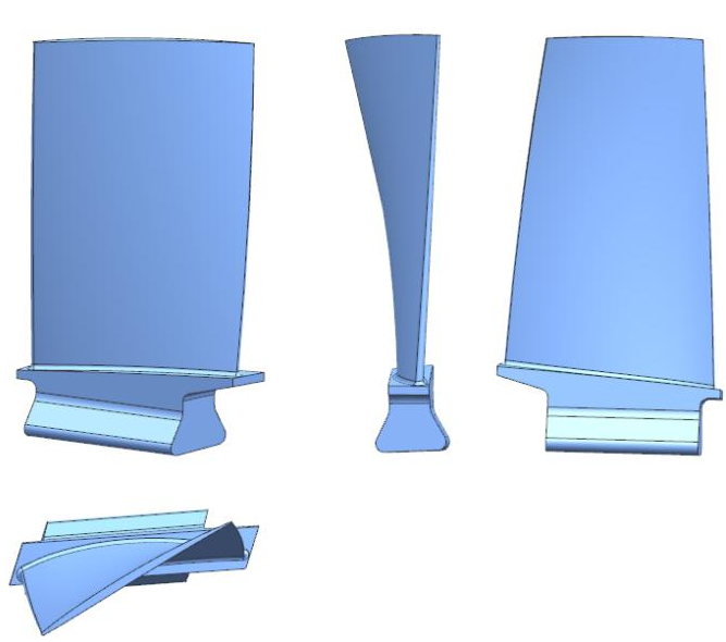
The first step in compressor blade DFM is understanding the geometry and functional requirements of the component.
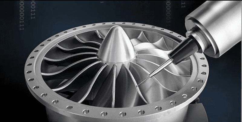
Compressor blades often feature complex three-dimensional surfaces designed to control airflow, pressure distribution, and aerodynamic efficiency. Unlike conventional machined components with relatively simple planar or cylindrical features, blade geometry can vary continuously along the span.
Important geometric features include:
Airfoil Profile: The cross-sectional shape that determines the aerodynamic characteristics of the blade.
Leading Edge: The front edge of the blade where airflow initially encounters the airfoil.
Trailing Edge: The rear edge where airflow leaves the blade.
Blade Twist: The variation in blade orientation from the root to the tip.
Blade Chord: The distance between the leading and trailing edges.
Blade Root: The mounting or attachment section connecting the blade to the rotor or supporting structure.
Blade Tip: The outermost section of the blade, where clearance and dimensional requirements may be important.
Each feature presents different manufacturing considerations.
For example, a twisted airfoil requires careful tool orientation during CNC machining. A thin trailing edge may be difficult to machine without deformation or edge damage. Meanwhile, the blade root may require precise dimensional control to ensure proper assembly.
Engineering consideration: Before finalizing the design, engineers should identify which geometric features are critical to aerodynamic performance, structural integrity, assembly, and inspection. These requirements should be clearly reflected in the CAD model and engineering drawing.
2. Wall Thickness: Balance Structural Requirements and Machinability
Wall thickness is one of the most important DFM considerations when designing compressor blades.
Thin-walled sections are often necessary to achieve aerodynamic requirements and minimize component weight. However, reducing material thickness can also reduce structural stiffness during machining.
When a thin blade section is subjected to cutting forces, it may deflect from its intended position. Once the cutting force is removed, the material may partially recover, resulting in dimensional deviations from the target geometry.
The risk becomes more significant when machining:
- Thin trailing edges
- Narrow airfoil sections
- Long, unsupported blade spans
- Areas with rapidly changing wall thickness
- Components made from materials with relatively low stiffness
What Should Engineers Consider?
2.1 Define Minimum Wall Thickness Based on Functional Requirements
Avoid specifying unnecessarily thin sections without considering their manufacturing implications.
The minimum wall thickness should be determined by aerodynamic, structural, material, and operating requirements. It should not be selected solely to make machining easier.
2.2 Avoid Abrupt Thickness Transitions Where Possible
Sudden changes in wall thickness can create local machining and inspection challenges.
Where the functional design permits, smoother transitions may help improve manufacturing consistency and reduce localized stress concentrations.
2.3 Consider Machining Support
Thin sections may require dedicated fixtures, additional support points, or carefully planned machining sequences.
These requirements should be considered during design rather than after the first machining trial.
2.4 Review the Machining Sequence
Material removal should be planned to maintain adequate stiffness throughout machining.
Roughing, intermediate machining, stress-relief operations where appropriate, and finishing may need to be arranged carefully according to the material and component geometry.
Important: There is no universal minimum wall thickness suitable for every compressor blade. Feasibility depends on material grade, blade dimensions, geometry, machine capability, cutting strategy, and workholding conditions.
3. Airfoil Geometry and Surface Continuity
The airfoil is the functional core of a compressor blade. Its profile directly influences the component’s aerodynamic behavior.
From a manufacturing perspective, however, the airfoil also determines machining accessibility, toolpath complexity, surface quality, and inspection requirements.
Three geometric characteristics deserve particular attention.
3.1 Airfoil Curvature
Highly curved surfaces require careful selection of cutting tools and machining strategies.
Small-radius regions may restrict tool access, while large curvature variations can affect tool engagement and surface consistency.
Engineers should review:
- Local surface curvature
- Concave and convex regions
- Transition areas between the airfoil and blade root
- Accessibility for finishing tools
- Potential tool interference
3.2 Leading and Trailing Edge Geometry
Leading and trailing edges often contain relatively small radii or thin sections.
These areas can be difficult to machine consistently, particularly when the blade geometry includes complex curvature or narrow edge thickness.
Designers should clearly define the intended edge geometry rather than leaving critical edge conditions ambiguous.
Where appropriate, the engineering drawing should specify:
- Edge radius
- Edge thickness
- Local profile tolerance
- Surface finish requirements
- Permitted edge break or deburring conditions
3.3 Surface Continuity
Unnecessary surface discontinuities can complicate toolpath generation and finishing.
For blade surfaces developed through multiple CAD patches, engineers should check whether the surface transitions are geometrically continuous and whether the CAD model accurately represents the intended airfoil.
A smooth-looking CAD model does not automatically guarantee a smooth machined surface. Toolpath strategy, tool geometry, machine dynamics, and cutting conditions all influence the final result.
4. Blade Twist and Five-Axis CNC Machining Accessibility

Many compressor blades incorporate geometric twist along their span.
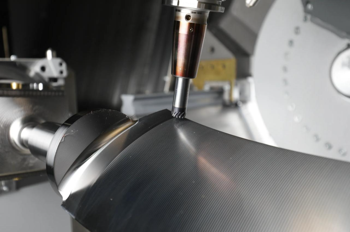
This means that the orientation of the airfoil changes from the root toward the tip. As a result, machining the complete blade surface may require changing the cutting tool orientation continuously.
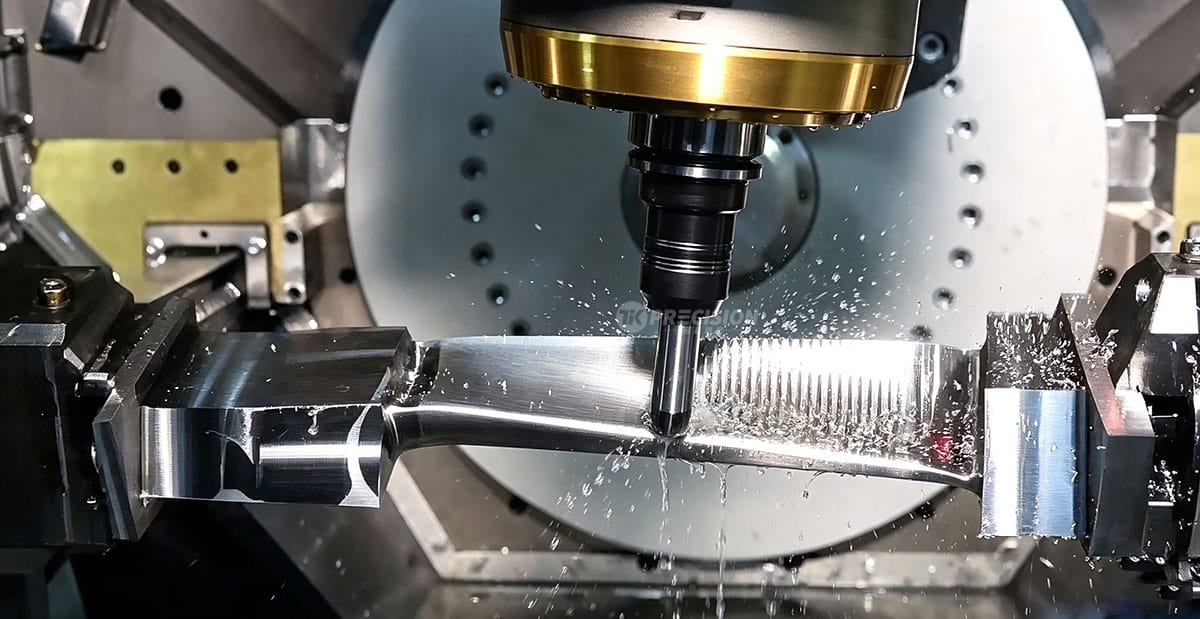
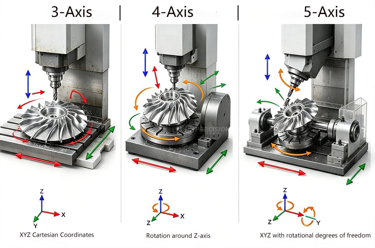
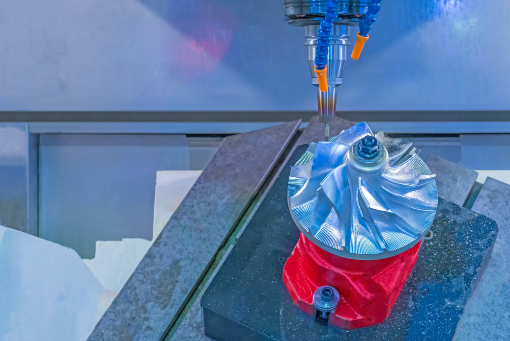
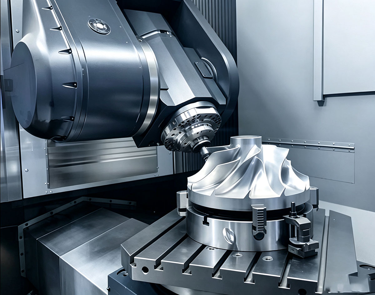
Five-axis CNC machining is particularly useful for these geometries.
Compared with conventional three-axis machining, simultaneous five-axis machining allows the cutting tool to maintain more suitable orientations relative to complex surfaces.
Potential manufacturing advantages include:
- Improved access to complex curved surfaces
- Reduced need for multiple repositioning operations
- Better control of tool contact conditions
- Opportunities to reduce fixture changes
- More efficient machining of complex blade geometries
However, five-axis machining does not automatically guarantee better accuracy or lower production costs.
The actual result depends on machine kinematics, rotary-axis calibration, fixture rigidity, tool length, toolpath quality, collision avoidance, and process planning.
What Should Engineers Consider During Design?
Tool Accessibility
Ensure that the airfoil geometry can be reached by practical cutting tools without excessive interference.
Tool Clearance
Review the clearance between the cutting tool, holder, fixture, and surrounding component geometry.
Fixture Accessibility
Consider whether the blade can be securely positioned while maintaining access to the surfaces that require machining.
Machining Datum Strategy
Identify suitable reference features for positioning the component during machining and inspection.
Early communication between the design and manufacturing teams can help identify difficult-to-machine areas before the prototype stage.
5. Blade Root Design and Assembly Requirements
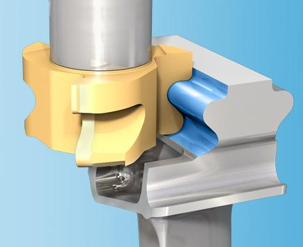
The blade root is another critical area that requires careful consideration during DFM.
Unlike the airfoil, which is primarily associated with aerodynamic performance, the root typically provides the mechanical connection between the blade and its supporting structure.
Depending on the compressor design, blade roots may incorporate:
- Dovetail profiles
- Fir-tree profiles
- T-shaped roots
- Other specialized attachment geometries
These features can involve complex machining operations and tight dimensional requirements.
Key DFM Considerations
5.1 Define Functional Datum Features
The blade root should have clearly identified reference surfaces or features that establish the relationship between the blade and its mating component.
5.2 Specify Critical Assembly Dimensions
Dimensions affecting fit, clearance, positioning, and load transfer should be clearly identified.
5.3 Consider Internal and Restricted Features
Deep grooves, narrow slots, and small internal radii may limit tool accessibility.
5.4 Review Inspection Accessibility
A feature that is difficult to machine may also be difficult to measure.
Engineers should consider how critical root dimensions will be inspected before finalizing the design.
For safety-critical or highly loaded compressor assemblies, root geometry and tolerances must also follow the applicable engineering and structural requirements. Manufacturing convenience should never override functional or safety requirements.
6. Material Selection: Consider Machinability as Well as Performance
Material selection has a direct influence on machining strategy, tool selection, cutting parameters, surface quality, and manufacturing cost.
Compressor blades may be manufactured from different materials depending on the operating environment, mechanical loading, temperature, corrosion resistance, and design requirements.
Common material families include:
| Material | Engineering characteristics | Manufacturing considerations |
|---|---|---|
| Stainless Steel | Corrosion resistance and mechanical strength | Work hardening and tool wear may require attention |
| Titanium Alloys | High strength-to-weight ratio | Low thermal conductivity and heat concentration require careful cutting strategies |
| Nickel-Based Alloys | High-temperature strength and corrosion resistance | Higher cutting forces and tool wear can increase machining difficulty |
| Aluminum Alloys | Low density and good machinability in many grades | Strength, fatigue, and operating-temperature requirements must be evaluated |
Material DFM Checklist
Before releasing the design for prototype machining, engineers should confirm:
- Exact material grade and specification.
- Material condition or heat-treatment requirements.
- Mechanical and operating-temperature requirements.
- Availability of the specified material.
- Machining characteristics of the selected grade.
- Required material certification and traceability.
- Compatibility with any subsequent surface treatment.
One important consideration is that material substitution should not be made solely to simplify machining.
Any proposed material change must be reviewed against the component’s functional, structural, and operating requirements.
7. Tolerances: Specify What Actually Matters
Overly tight tolerances can increase machining time, inspection requirements, and manufacturing costs.
However, tolerances that are too loose may affect blade performance, assembly, or functional reliability.
The objective of tolerance planning is not to make every dimension as precise as possible. It is to ensure that every critical feature has the appropriate level of dimensional control.
7.1 Identify Critical-to-Function Dimensions
For compressor blades, important dimensions may include:
- Airfoil profile
- Leading and trailing edge geometry
- Blade thickness
- Blade root dimensions
- Root-to-airfoil positional relationships
- Overall blade height and span
- Relevant assembly reference dimensions
7.2 Use Geometric Dimensioning and Tolerancing (GD&T)
GD&T helps communicate the allowable variation in geometric features and their relationships.
Depending on the design, relevant controls may include:
- Profile of a surface
- Position
- Perpendicularity
- Parallelism
- Flatness
- Runout
Not every control is required on every blade. The selection should reflect actual functional requirements and the intended inspection method.
7.3 Establish Practical Inspection Requirements
Before assigning a tight tolerance, consider whether the feature can be measured reliably.
For complex airfoil surfaces, inspection may involve CMM measurement, scanning systems, or optical measurement equipment.
The measurement method should be capable of evaluating the specified geometry with appropriate measurement uncertainty.
Engineering recommendation: Clearly distinguish critical dimensions from non-critical dimensions on the drawing. This helps manufacturing teams allocate machining and inspection resources where they provide the greatest functional value.
8. Surface Finish and Edge Quality
Surface finish is an important consideration in compressor blade manufacturing.
Surface irregularities may affect aerodynamic performance, while burrs and edge defects can create additional assembly or operational concerns.
The required finish depends on the component’s design, application, operating conditions, and engineering specifications.
Engineers should clearly define:
- Surface roughness requirements
- Surfaces requiring controlled finishing
- Leading and trailing edge conditions
- Burr removal requirements
- Coating or surface treatment specifications, where applicable
It is also important to distinguish between surface roughness and geometric accuracy.
A blade may have a smooth surface while still deviating from its intended airfoil profile.
For this reason, surface finish inspection and dimensional profile inspection should be treated as separate quality requirements.
9. Design for Fixturing and Workholding
Fixture design is often overlooked during the initial design stage.
However, compressor blades can be difficult to hold securely because of their curved surfaces, slender geometry, and changing cross-sections.
An unsuitable workholding strategy may cause:
- Component movement during machining
- Localized deformation from clamping pressure
- Reduced machining stability
- Restricted tool access
- Difficulties maintaining consistent reference positions
What Should Engineers Consider?
Establish Practical Reference Surfaces
Where the design allows, include suitable datum features that support repeatable positioning.
Consider Temporary Manufacturing Features
For certain prototypes, temporary tabs or additional machining stock may help with workholding. These features must be compatible with the final design and subsequent machining operations.
Avoid Unnecessary Clamping Pressure
Thin or unsupported blade sections may deform under excessive fixture pressure.
Consider Multiple Machining Setups
Some complex blade geometries may require different workholding arrangements to access all required surfaces.
Fixture planning should be part of the manufacturing feasibility review, particularly when producing the first prototype.
10. Design for Inspection: Make Critical Features Measurable

A component is not fully manufacturable simply because it can be machined.
It must also be possible to verify that the finished part meets the engineering drawing.
This is especially important for compressor blades because of their complex three-dimensional geometry.
Common Inspection Methods
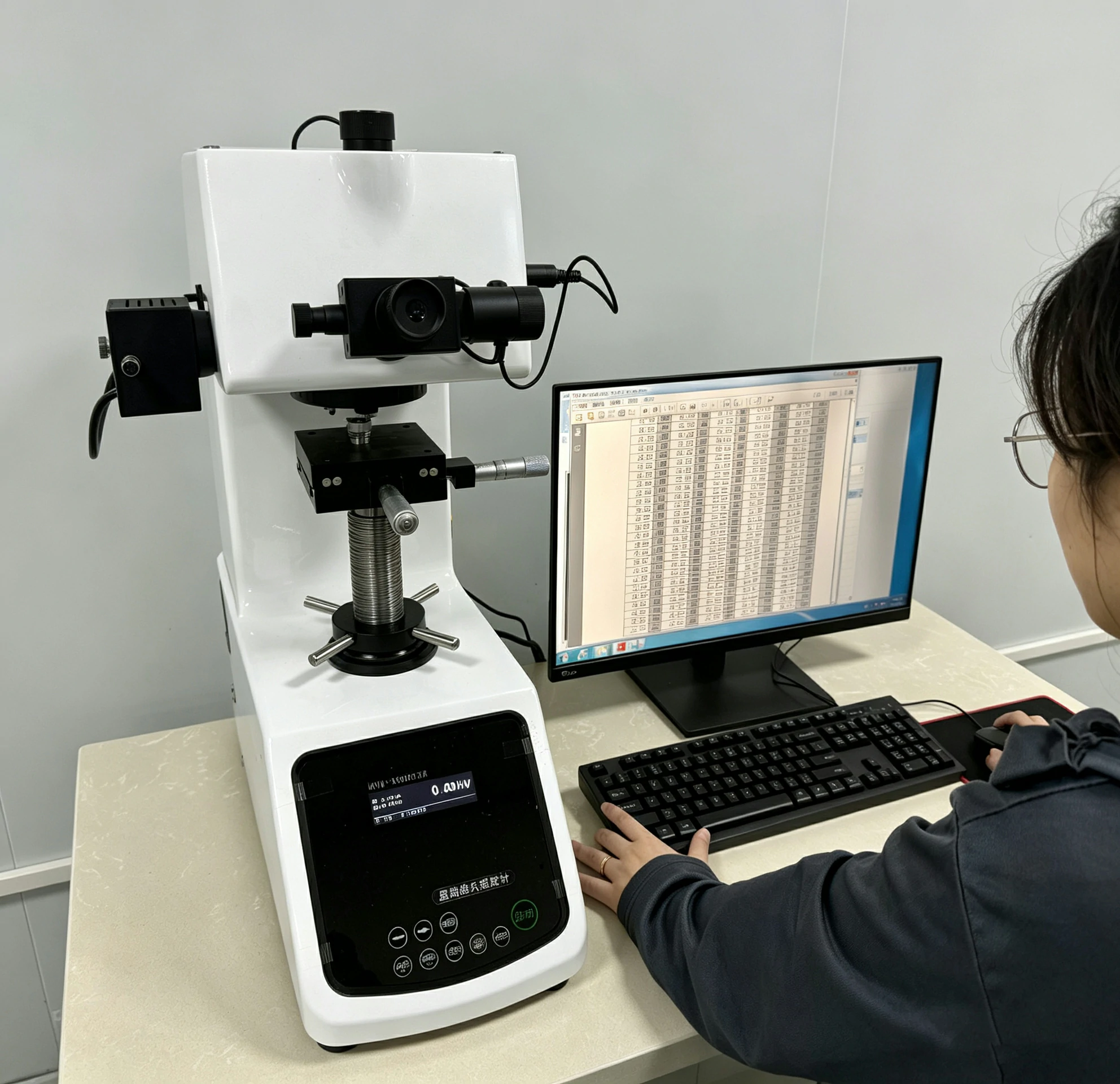
Coordinate Measuring Machine (CMM)
A CMM can be used to measure selected geometric features and evaluate dimensional deviations against the engineering drawing or CAD reference.
Optical Measurement
Optical systems can be useful for measuring certain small features, edge geometries, and accessible profiles.
3D Scanning
Depending on the equipment and inspection requirements, 3D scanning can provide surface data for comparison with the nominal CAD geometry.
What Should Be Defined in the Drawing?
- Critical measurement locations
- Datum reference system
- Profile tolerance requirements
- Blade thickness measurement locations
- Root dimensional requirements
- Surface roughness specifications
- Required inspection documentation
The inspection method should be selected according to the geometry, tolerance requirements, accessibility, and measurement uncertainty.
A complete inspection plan should be considered before manufacturing begins, not after the prototype has been completed.
11. From CAD Model to CNC Machined Prototype: A Practical DFM Workflow
For new compressor blade development, a structured engineering review can help identify manufacturing risks before machining begins.
A typical workflow may include the following stages.
Step 1: CAD Model Review
Review the 3D model for geometry completeness, surface continuity, feature accessibility, and potential machining restrictions.
Step 2: Engineering Drawing Review
Check dimensions, GD&T, material specifications, surface finish requirements, and critical functional features.
Step 3: Manufacturing Feasibility Assessment
Evaluate the proposed machining process, workholding strategy, tool accessibility, and material removal requirements.
Step 4: Machining Strategy Development
Determine the appropriate roughing, semi-finishing, finishing, and inspection sequence.
Step 5: Prototype Machining
Manufacture the initial component using the approved CAD model, engineering drawing, and machining plan.
Step 6: Dimensional Inspection
Verify critical dimensions and geometric features using suitable measurement equipment.
Step 7: Engineering Feedback
Compare inspection results with design requirements and communicate any manufacturing observations that may be relevant to subsequent design revisions.
This process helps connect product design with practical manufacturing considerations.
12. Engineering DFM Checklist Before Releasing a Compressor Blade for Manufacturing

Before sending a compressor blade design for CNC machining, engineers can use the following checklist to review the most important manufacturing considerations.
| Review Item | What to Check |
|---|---|
| CAD Model | Complete 3D geometry and valid surfaces |
| Airfoil Profile | Defined profile and critical geometric requirements |
| Wall Thickness | Minimum thickness and local variations |
| Leading Edge | Edge radius and thickness requirements |
| Trailing Edge | Edge geometry and machining feasibility |
| Blade Twist | Tool accessibility and machining orientation |
| Blade Root | Attachment geometry and critical dimensions |
| Material | Exact grade, condition, and certification |
| Tolerances | Functional dimensions and GD&T |
| Surface Finish | Defined roughness and finishing requirements |
| Workholding | Suitable datums and fixture accessibility |
| Tool Accessibility | Tool clearance and potential interference |
| Inspection | Measurement method and inspection requirements |
| Documentation | Complete drawings and revision information |
A well-prepared design package reduces ambiguity during quotation, manufacturing planning, and prototype inspection.
Conclusion: Good Blade Design Should Consider Manufacturing from the Beginning
Compressor blade development requires a close relationship between engineering design and manufacturing.
Airfoil geometry, wall thickness, material selection, blade root configuration, tolerances, and inspection requirements all influence whether a design can be manufactured consistently.
Addressing these considerations early can help engineering teams identify potential manufacturing challenges before committing to prototype production.
For engineers developing new compressor blades, involving a precision machining manufacturer during the design review stage can provide valuable feedback on machining accessibility, workholding, tolerances, and inspection planning.
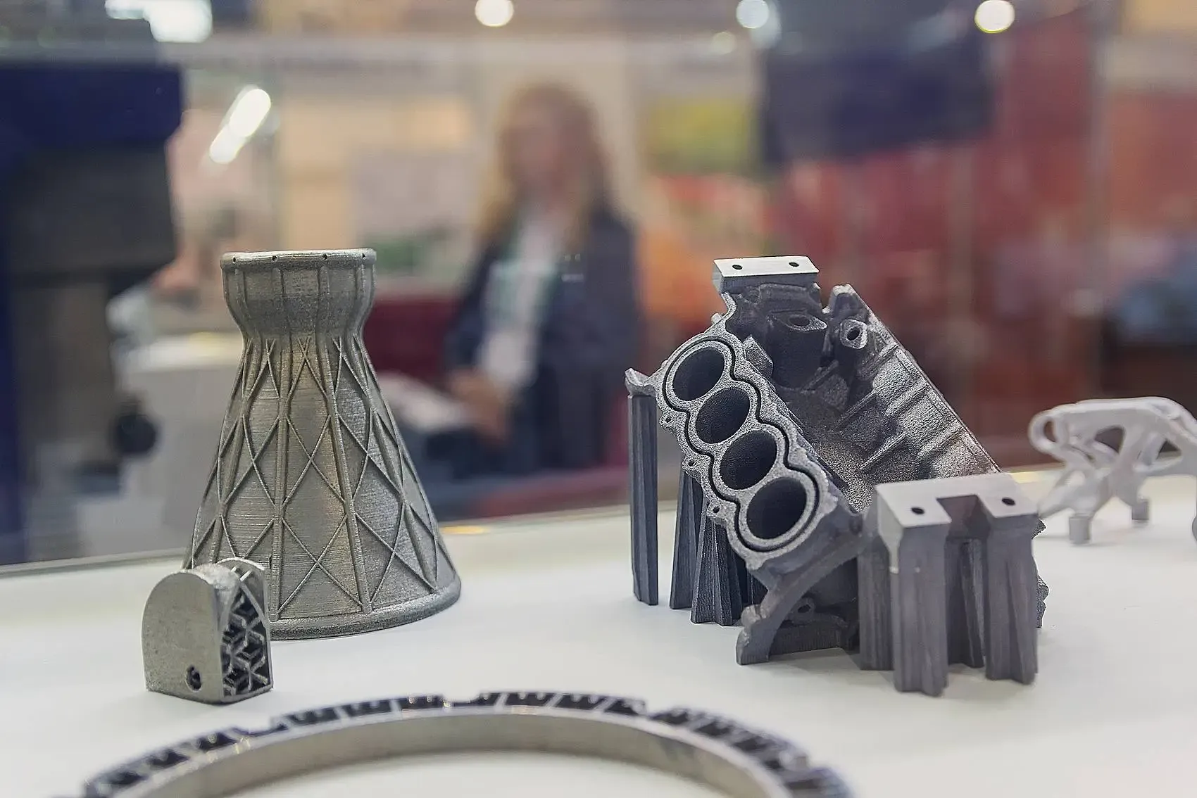
At TikPrecision, we work with customer CAD models and engineering drawings to manufacture custom precision-machined components across different industries. Our CNC milling, turning, and five-axis machining capabilities support the production of complex geometries, prototype components, and low-volume parts.
Developing a New Compressor Blade or Other Complex Precision Component?
Share your 3D CAD model and engineering drawing with TikPrecision. We can review the manufacturing requirements and discuss suitable machining approaches for your project.
[Submit Your CAD Drawing] · [Request a Manufacturing Review]
Frequently Asked Questions
DFM helps engineers identify potential machining, workholding, tolerance, and inspection challenges before production. This can reduce avoidable design revisions and improve prototype manufacturing feasibility.
Yes. Five-axis CNC machining is suitable for many complex compressor blade geometries, particularly twisted airfoil surfaces. The actual machining strategy depends on the component geometry, material, machine capability, and inspection requirements.
Ideally, engineers should provide a 3D CAD model, fully dimensioned engineering drawing, material specification, critical tolerances, surface finish requirements, and estimated quantity.
Engineers should balance structural and aerodynamic requirements with machining stiffness, workholding conditions, material properties, and the planned machining sequence. Minimum wall thickness should be determined by the specific application rather than a universal machining rule.
Depending on the required tolerances and geometry, inspection may involve CMM measurement, optical measurement, and 3D scanning. The appropriate method should be selected according to the critical features and measurement requirements.
Yes. A manufacturing review can evaluate geometry, tool accessibility, workholding considerations, material selection, tolerance requirements, and inspection feasibility before prototype production begins.