CNC Machining Tolerances Guide | Precision Standards & Cost Optimization

Understanding CNC Machining Tolerances

1. Introduction: Why Tolerances Matter in CNC Machining

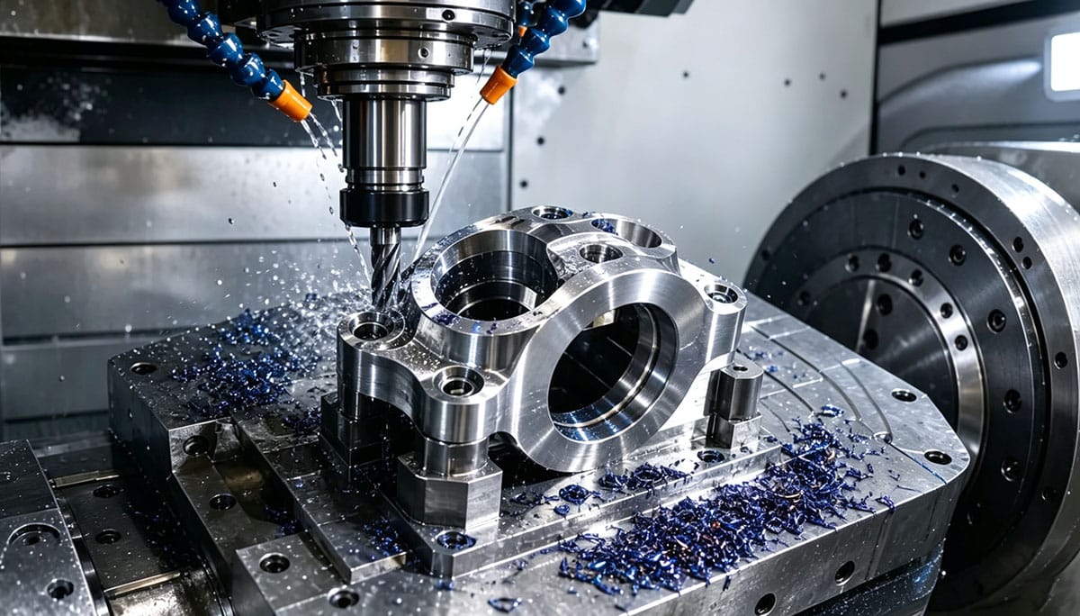
In CNC machining, tolerances define the permissible limit of variation in a physical dimension—essentially, how much a part can deviate from its specified measurement without impacting functionality. While the numbers may seem small, the implications are huge.

For example, a component designed to fit tightly within another might require a tolerance as tight as ±0.01 mm. A looser fit, on the other hand, might allow a tolerance of ±0.1 mm. Choosing the right tolerance is critical to ensure that parts fit, move, or seal as expected—especially in high-performance sectors like aerospace, automotive, or medical devices.

Most importantly, tight tolerances increase machining complexity and cost. Every micron of precision requires more time, inspection, and specialized tools. Therefore, balancing functionality and manufacturability is a key part of design-for-manufacturing (DFM) strategies.

 A well-toleranced part minimizes production waste, shortens lead times, and reduces quality issues—making tolerance planning a foundational step in CNC part design.


2. Common Types of Tolerances in CNC Machining

CNC machining tolerances fall into several categories, each serving different aspects of dimensional and functional control. Understanding the differences helps engineers select appropriate standards for specific parts and features.

Linear Tolerances

Linear tolerances control variations in straight-line distances—such as the length, width, or height of a part. They are typically denoted as:

 ±0.1 mm

For example, a part with a specified dimension of 50 mm and a tolerance of ±0.1 mm must fall between 49.9 mm and 50.1 mm.

Linear tolerances are the most commonly applied in CNC drawings and can range from loose (±0.5 mm) to tight (±0.01 mm), depending on the application.

Angular Tolerances

Angular tolerances specify allowable variation in degrees for angles, such as bevels, chamfers, or sloped surfaces. A tolerance of ±1° means the actual angle may vary within a 2-degree window.

While not as frequent as linear tolerances, angular control is crucial for mating features, rotating components, or draft angles in molded parts.

Geometric Tolerances (GD&T)

Geometric Dimensioning and Tolerancing (GD&T) offers a more advanced method of tolerance specification. Rather than just dimensions, it defines the form, orientation, location, and runout of part features. Key types include:

  • Flatness – ensuring a surface lies within two parallel planes.

  • Perpendicularity – controlling how perpendicular a surface or axis is.

  • Position – defining a feature’s exact location relative to a datum.

  • Cylindricity – controlling roundness and straightness along a cylinder.

GD&T is essential when working with complex geometries, tight assemblies, or multi-axis CNC machining, as it allows for greater control and clear communication between design and production teams.


3. How to Define Appropriate Tolerances for Your Design

Choosing the right tolerance is a balancing act between design intent, functional needs, and production capability. Overly tight tolerances can unnecessarily drive up costs, while loose ones may result in parts that don’t fit or function properly.

Here’s how to approach tolerance selection effectively:

Start with the Function of the Part

Begin by asking: What does this part need to do? If it’s a cosmetic cover, a ±0.5 mm tolerance might be fine. If it’s a gear shaft for an automotive application, you may need tolerances as tight as ±0.01 mm or even tighter.

 Tolerances should reflect the criticality of a feature—not all dimensions need to be held to the same level of precision.

Match Tolerances to Manufacturing Capabilities

Most CNC machines can hold general tolerances of:

  • ±0.127 mm (±0.005 in) as a standard

  • ±0.025 mm (±0.001 in) with additional setup, tool wear control, and inspection

Before specifying ultra-tight tolerances, consult your machining partner to confirm what’s achievable without excessive cost or rejection rates.

Consider the Material Being Machined

Different materials behave differently under machining. For example:

  • Aluminum is easy to cut and maintains tight tolerances.

  • Stainless steel may expand with heat and be harder to hold consistently.

  • Plastics can deform under cutting forces or post-machining stress.

Thermal expansion, warping, or internal stress release can all affect final dimensions—so design tolerances must take the material’s machinability into account.

Anticipate Secondary Operations

Processes like anodizingplating, or heat treatment can alter part dimensions slightly. If a part will undergo these treatments, tolerances must be adjusted accordingly or post-treatment machining may be necessary.


4. Inspection Methods for Verifying Tolerances

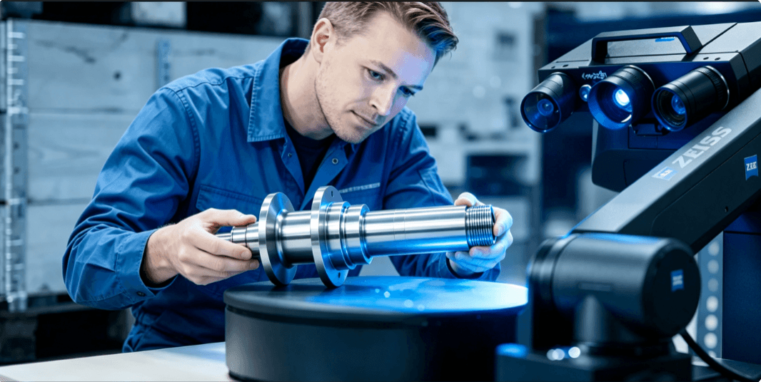
Accurate verification of CNC tolerances is critical for ensuring part quality and meeting design specifications. Depending on the required precision and complexity of the geometry, various inspection tools and techniques can be applied.

Basic Inspection Tools

For most general tolerance checks (±0.1 mm or more), conventional tools are sufficient:

  • Calipers (digital or vernier) – Used for quick, accurate measurements of outer dimensions, hole sizes, and depths (typically accurate to ±0.02 mm).

  • Micrometers – Provide higher precision for smaller or critical dimensions, accurate to ±0.01 mm or better.

  • Height gauges and dial indicators – Used for inspecting flatness, perpendicularity, and parallelism on machined surfaces.

These tools are ideal for parts with relatively simple geometries and accessible features.

Advanced Dimensional Inspection

For tighter tolerances, complex parts, or when verifying geometric tolerances (GD&T), more sophisticated methods are required:

  • Coordinate Measuring Machines (CMM)
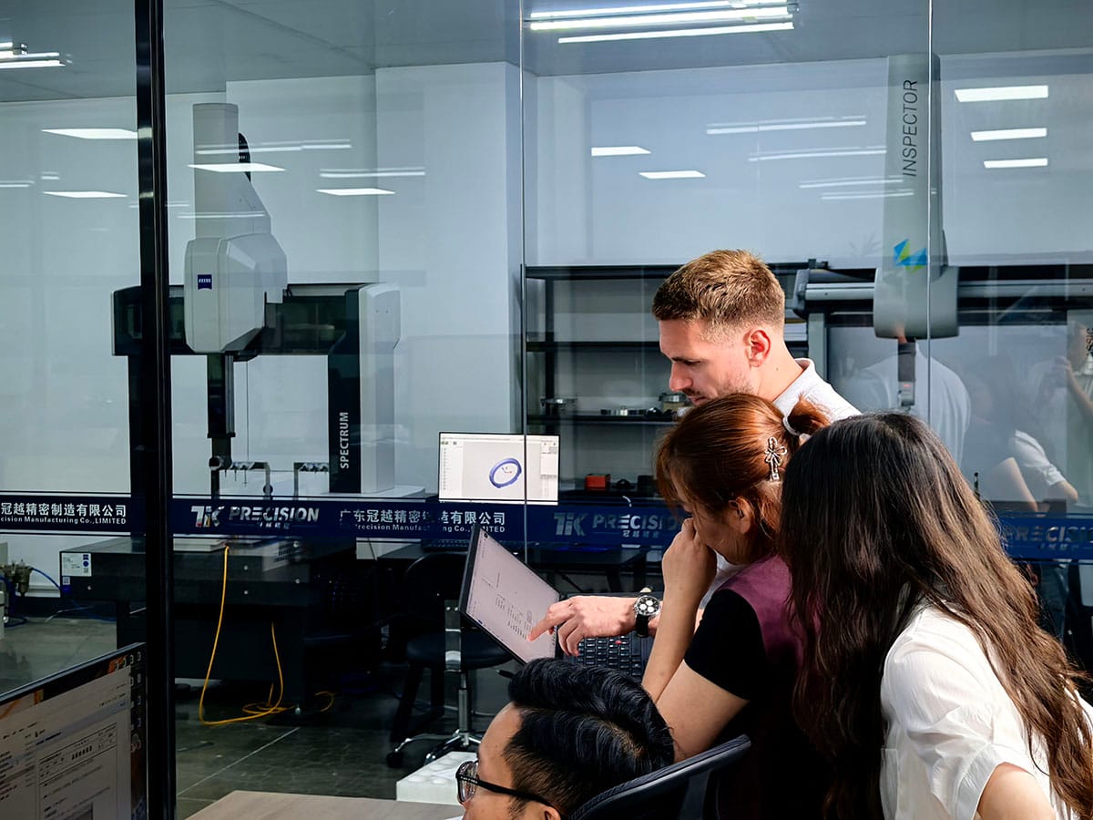
    CMMs use a probe (touch-trigger or laser) to capture 3D coordinates of part surfaces and features. They are essential for high-precision parts, particularly those with tight position, flatness, or roundness tolerances.

  • Optical Comparators
    These devices project a magnified silhouette of the part onto a screen, allowing inspection of profiles and dimensions against a digital or physical overlay.

  • 3D Scanning / Laser Metrology
    Useful for freeform surfaces and organic geometries where traditional tools can’t reach. These scanners generate a complete 3D model of the part, which is then compared to the CAD model for tolerance verification.

Inspection Reporting

In precision manufacturing, especially for regulated industries like aerospace or medical, customers often require formal documentation such as:

  • First Article Inspection (FAI) reports

  • Dimensional Inspection Certificates

  • Quality Control (QC) summaries

These reports typically list the inspected features, their tolerances, measured results, and whether they pass or fail.


5. Best Practices for Tolerance Optimization in CNC Projects

Specifying tight tolerances across all dimensions may sound like a safe design choice—but in practice, it can lead to unnecessary costs, extended lead times, and even higher rejection rates. Here are some practical strategies to help you optimize tolerances without compromising part performance:

1. Apply Tight Tolerances Only Where Necessary

Critically evaluate each dimension: is tight control essential for function, fit, or performance?

Apply ±0.01 mm–0.05 mm only to high-precision features such as:

  • Press fits

  • Bearing surfaces

  • Sealing interfaces
Use looser tolerances (±0.1 mm or greater) for non-critical features:
  • Cosmetic faces
  • Non-mating surfaces
  • Relief grooves or cutouts

This selective approach reduces inspection time and machining costs.

2. Design for Manufacturability (DFM)

Simplify geometries where possible:

  • Avoid unnecessarily deep pockets or thin walls.

  • Maintain consistent wall thickness.

  • Design features that are accessible from common toolpaths—especially for 3-axis machining.

Collaboration with your CNC supplier during the design stage can reveal opportunities to ease tolerances while still meeting design intent.

3. Use GD&T for Critical Geometry

Geometric Dimensioning and Tolerancing (GD&T) allows for a more precise control of form, orientation, and position than traditional ± tolerances.

  • For instance, instead of specifying flatness with a tight ± dimension, use a flatness callout that may allow more flexibility.

  • GD&T ensures functional requirements are met, while reducing the likelihood of over-tolerancing.

4. Communicate Tolerance Priorities

Clearly mark critical-to-function (CTF) dimensions in your 2D drawing or CAD model. This helps CNC machinists and inspectors focus their attention on what truly matters, improving accuracy and delivery reliability.

Lorem ipsum dolor sit amet, consectetur adipiscing elit. Ut elit tellus, luctus nec ullamcorper mattis, pulvinar dapibus leo.

On This Page
Need a Manufacturing Quote?

Upload your drawings and receive DFM feedback, material recommendations, and a clear manufacturing quote.

Request a Quote
Related Articles
5-axis machining services for complex impellers and precision metal parts

The Ultimate Guide to 5-Axis CNC Machining: Precision, Efficiency, and Applications

In the Energy and Power Generation sector, components must withstand extreme thermal stresses and high pressures. Similarly, in the Medical Technology field, 5-axis CNC

Swiss CNC machining process using a guide bushing to manufacture high-precision metal components

The Evolution of Precision CNC Machining Services for Modern Industry

In high-stakes industries like aerospace and medical device manufacturing, precision CNC machining services are the indispensable backbone of modern innovation. As engineering requirements push

Precision CNC Machining Prototyping Services for Industrial Parts

Next-Gen CNC Machining: Driving Innovation through Precision Prototyping

CNC Machining Prototyping has become an invaluable tool in the product development phase, offering high-speed, precise, and flexible production for a wide range of

Start a New Project

Turn Your CAD Files Into Precision Parts

Share your requirements with our engineering team. We will review manufacturability, materials, tolerances and lead time before quoting.

2-Hour Quote

Fast response for complete RFQs

Free DFM Review

Engineering feedback before production

Secure CAD Files

Confidential upload and NDA support

No MOQ

Prototype to low-volume production

Need help preparing an RFQ?

info@tikprecision.com

RFQ Form

Tell Us About Your Project

This preview uses standard controls that can later be rebuilt with the Elementor Pro Form widget.