Design for Manufacturability — DFM — is the practice of designing parts that are easy to produce. Applied to CNC machining, DFM bridges the gap between CAD idealization and shop-floor reality. A DFM-optimized part costs less, arrives faster, and performs more consistently than one designed without manufacturing constraints in mind. This guide covers the fundamental DFM principles every mechanical engineer should apply before sending a part out for quote.
Principle 1: Design for the Largest Practical Tool
Every machining operation begins with tool selection, and tool diameter dictates everything: material removal rate, surface finish, corner radii, and cycle time. A 12 mm end mill removes material roughly 8 times faster than a 3 mm end mill in the same material.
Rule of thumb: For any feature, ask yourself — what is the largest tool that can produce this geometry? Design internal corners, pocket floors, and cavity widths to accommodate that answer.
| Feature | Recommended Minimum Radius |
|---|---|
| Internal corner (aluminum) | ≥ 3 mm or 1/3 pocket depth, whichever is larger |
| Internal corner (steel) | ≥ 2 mm or 1/4 pocket depth |
| Pocket floor-to-wall radius | ≥ 1 mm (avoid sharp corners) |
| Undercut groove width | Match standard T-slot cutter sizes |
Pro tip: If your part has both large and small internal radii, the machinist must either use multiple tools (increasing cycle time) or use the smallest radius everywhere (slowing every operation). Standardize radii across the part wherever function permits.
Principle 2: Minimize Tool Changes and Setups
Every tool change costs time — 15-30 seconds for an automatic tool changer, far more for manual changeover. Every re-fixturing operation costs even more: 15-60 minutes of setup labor plus the risk of positioning error.
- Use the same hole size wherever possible. If your part needs M4 and M5 threaded holes, consolidate on M5 if the smaller size is not critical.
- Keep hole depths consistent. Drilling to 10 different depths requires 10 different drill cycles. Design to standard depth increments.
- Place all features requiring the same tool on the same face or within the same setup whenever possible.
- Consider 5-axis machining if your part requires features on 4+ faces — the single-setup advantage often outweighs the higher machine rate.
Principle 3: Understand and Control Tolerances
This cannot be emphasized enough: over-tolerancing is the most expensive design mistake in CNC machining. The relationship between tolerance and cost is non-linear.
- General tolerances: ±0.1 mm is achievable on any competent CNC machine without special effort.
- Precision tolerances: ±0.025 mm requires careful tool selection, slower feeds, and frequent measurement.
- High-precision tolerances: ±0.005 mm demands temperature control, grinding or hard turning, and CMM verification.
Best practice: Use geometric dimensioning and tolerancing (GD&T) to define exactly what matters — true position for hole patterns, flatness for sealing surfaces, perpendicularity for bearing bores. Apply tight tolerances only to the features that actually require them, and reference all critical dimensions from a clearly defined datum structure.
Principle 4: Respect Material Behavior
Different materials machine differently, and designs that work perfectly in aluminum may be impractical in stainless steel or titanium.
- Aluminum: Forgiving. Thin walls (≥1.0 mm), deep pockets (up to 6:1 depth-to-diameter ratio), and fine threads are all practical.
- Stainless steel: Work-hardens at the cut. Requires rigid setups, sharp tools, and consistent feed rates. Minimum wall thickness: 1.5 mm.
- Titanium: Poor thermal conductivity concentrates heat at the tool tip. Requires low cutting speeds and generous corner radii to prevent tool failure. Budget 3-5x the cycle time of steel.
- Plastics: Stress-relief during machining can warp thin sections. Account for thermal expansion (PEEK expands 5x more than steel per degree Celsius). Use sharp tools to prevent melting and burr formation.
Principle 5: Design Threaded Features Intelligently
Threaded holes are among the most common features in CNC parts — and among the most common sources of manufacturing problems.
- Through-holes are preferred over blind holes. They allow chips to exit, eliminate bottom-tapping issues, and simplify inspection.
- For blind threaded holes: Allow at least 3x the thread diameter for the tap drill depth beyond the threaded portion. This clearance prevents tap breakage and ensures full thread form at the bottom of the tapped section.
- Avoid threading to the bottom of a blind hole. The last few threads of a tap are incomplete, and they need room to taper out.
- Choose coarse threads over fine threads unless fine adjustment is mechanically necessary. Coarse threads are stronger, more resistant to stripping, and faster to produce.
Principle 6: Think About Inspection During Design
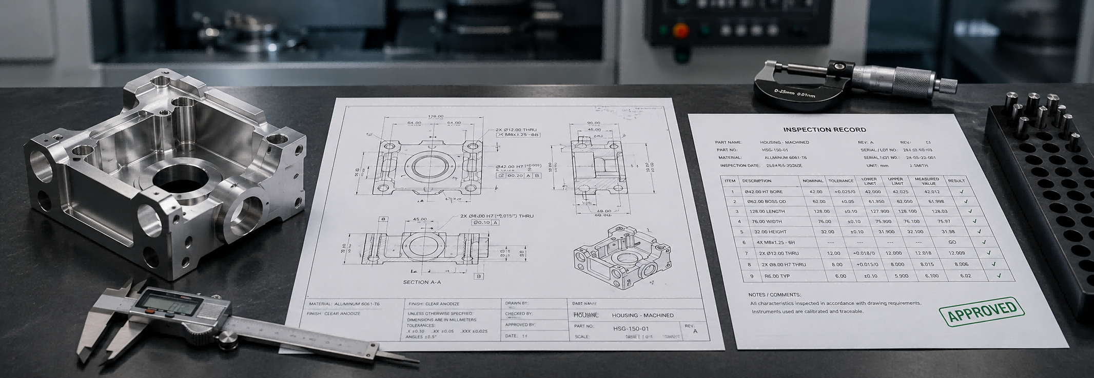
A part that cannot be measured cannot be verified. During DFM, consider how each dimension will be checked:
- Caliper-accessible features for standard dimensions.
- Pin gauge or thread gauge for hole diameters and threads.
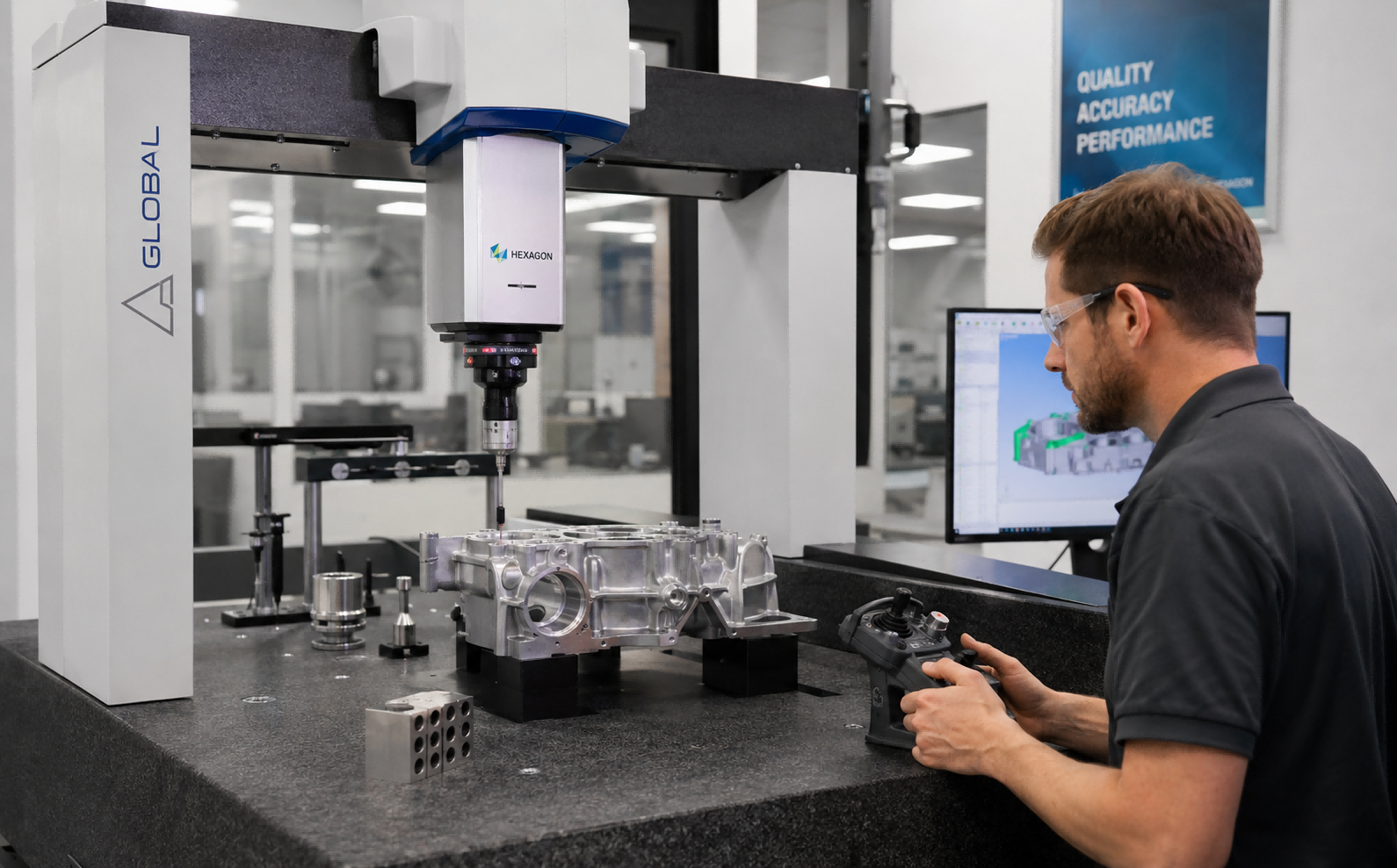
- CMM (Coordinate Measuring Machine) for complex geometries and GD&T callouts.
- Optical comparator or vision system for small features and edge profiles.
If a critical dimension cannot be inspected with standard metrology equipment, the part cannot be reliably manufactured — regardless of how well-designed it appears on screen.
DFM Checklist: Before You Send It Out
- Are all internal corner radii specified and ≥ 3 mm where possible?
- Are tolerances applied only where functionally required?
- Can the part be machined in 3 setups or fewer?
- Are threaded holes through wherever possible, with standard sizes?
- Is the minimum wall thickness appropriate for the selected material?
- Have you specified surface finish requirements explicitly?
- Are all critical dimensions inspectable with standard metrology tools?
- Have you provided a STEP file alongside the 2D drawing?
At Tik Precision, every quote includes a free DFM review. Our engineers will flag potential cost drivers in your design and suggest alternatives — before a single chip is cut. Upload your CAD files to get started.