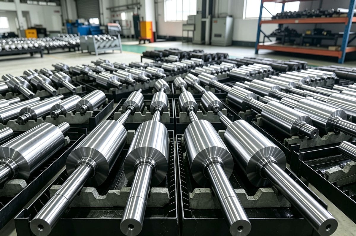
Shafts connect rotating machinery to the world: they carry impellers, rotors, gears, and couplings; they transmit torque; and they ride in bearings that demand near-perfect geometry. From compressor shafts and pump shafts to turbine shafts and motor spindles, precision CNC shaft machining is what keeps machines quiet, efficient, and reliable.
This guide covers how precision shafts are machined to print, which tolerances are actually achievable, why grinding is essential for the tightest features, and what inspection documentation protects you when the shaft arrives.
Why Shaft Precision Matters
A shaft is simple to describe but demanding to manufacture. The rotating assembly depends on the shaft’s geometry in every direction:
- Journal roundness and cylindricity determine how evenly the bearing load is distributed
- Runout (TIR) directly creates vibration if it exceeds design limits
- Concentricity between journals controls how straight the whole rotating assembly runs
- Surface finish on journals affects oil film thickness in hydrodynamic bearings
- Step and shoulder squareness affects how impellers and couplings seat
At high speeds, a few microns of error becomes measurable vibration, noise, and heat. That is why precision shafts are ground, measured, and documented rather than simply turned.
The Precision Shaft Machining Process
A precision shaft moves through a controlled sequence:
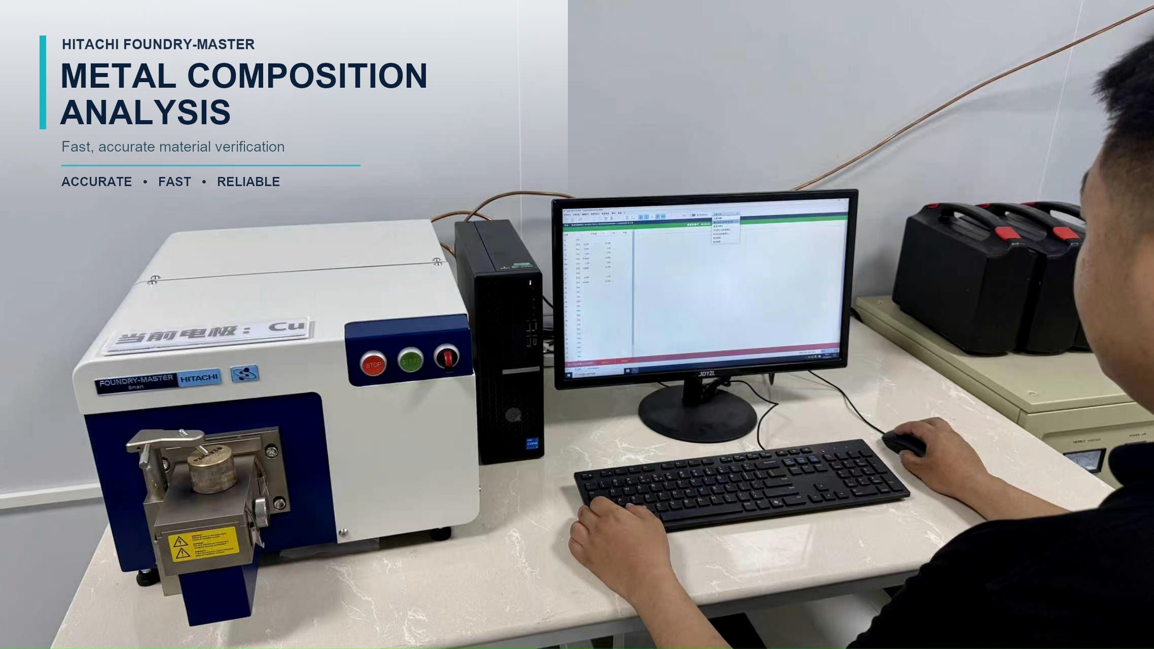
- Material verification — grade, heat number, hardness, and straightness are checked before cutting.
- Center preparation — both ends are center-drilled so the part can be turned and ground on its true axis.
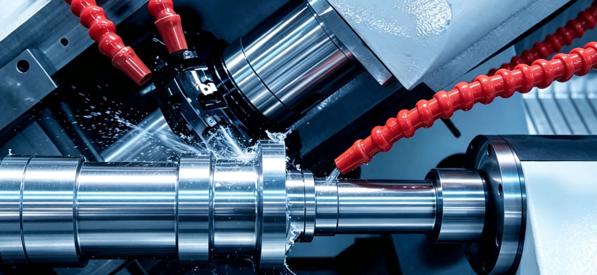
- Rough turning — removes bulk material in stages, controlling heat and internal stress.
- Stress relief (where specified) — reduces residual stress that would cause the shaft to move after machining.
- Semi-finish turning — brings all diameters near final size.
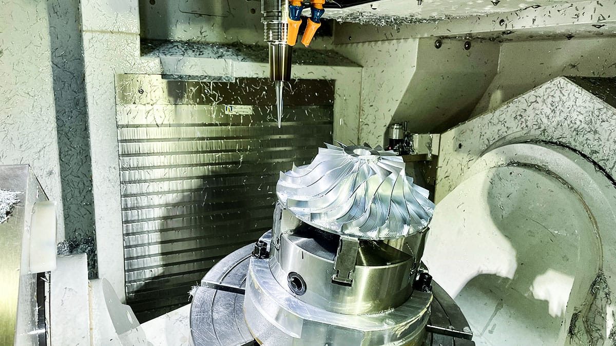
- Precision grinding — journals, seal diameters, and other critical features are ground to final tolerance and finish.
- Secondary operations — keyways, splines, threads, and cross holes are added on mill-turn machines.
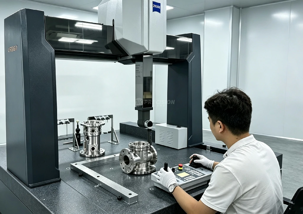
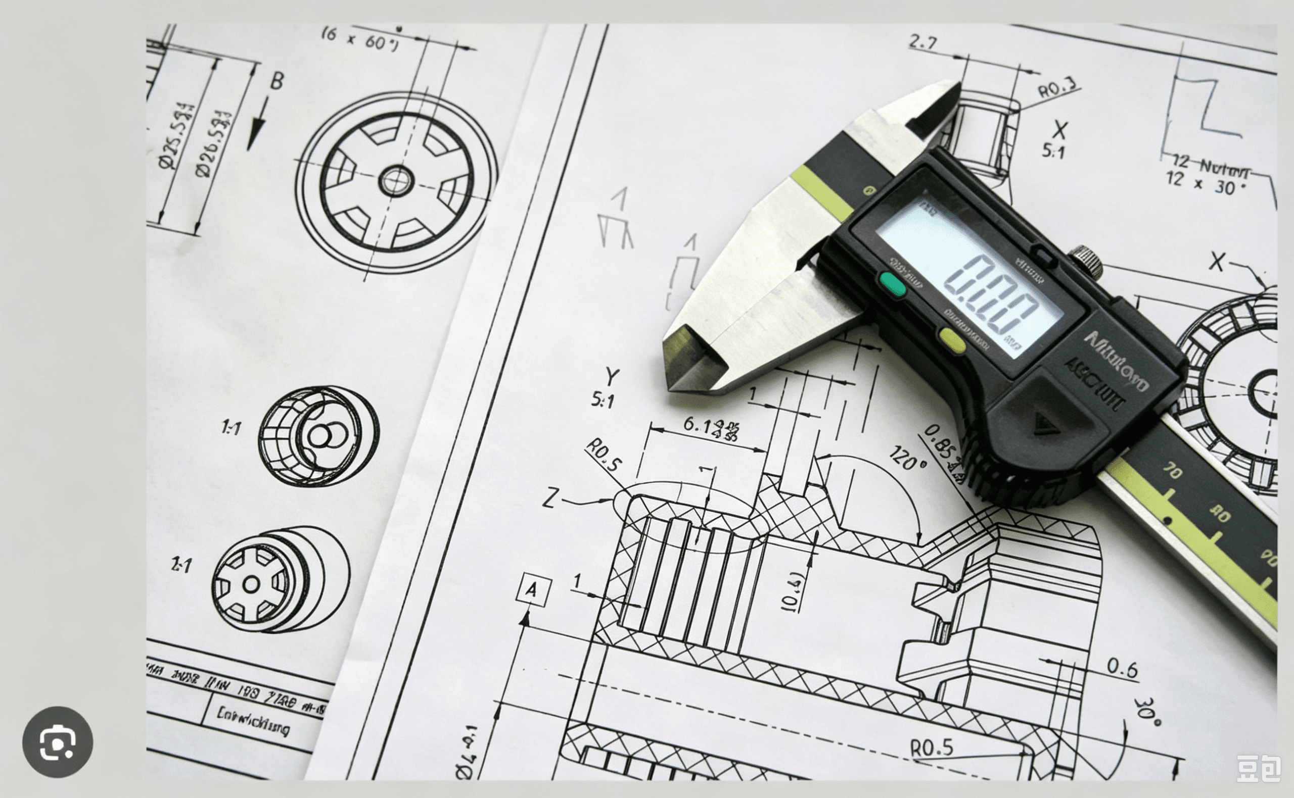
- Final measurement — Zeiss CMM, roundness, and surface finish checks confirm the part meets the drawing.
Throughout the process, the shaft stays referenced to its centers so that every feature is positioned relative to the true rotation axis.
Tolerance Capability for Precision Shafts
Shaft tolerances depend on feature type and shaft size:
| Feature | Achievable capability | Typical production tolerance |
|---|---|---|
| Ground journal diameter | ±0.002 mm | ±0.005 mm |
| Runout (TIR) on journals | 0.002–0.005 mm | 0.005–0.01 mm |
| Concentricity between journals | Micron level | 0.005–0.02 mm |
| Roundness | 0.001–0.003 mm | 0.003–0.008 mm |
| Surface finish | Ra 0.1–0.2 µm | Ra 0.2–0.8 µm |
| Keyway width | ±0.01 mm | ±0.02 mm |
Every quote states clearly which features will be ground and which will be turned, so you know exactly what capability you are paying for.
Grinding vs. Turning: When Each Is Used
Turning and grinding are complementary, not competing:
- CNC turning handles roughing, semi-finishing, steps, threads, and most geometry quickly and economically
- Cylindrical grinding is required for ±0.002 mm diameters, micron-level roundness, and fine surface finishes
- Grinding between centers corrects errors left by turning and achieves the tightest runout
- Internal grinding finishes bores and internal tapers that must stay concentric with the outside
If your drawing calls out tight journal tolerances, the DFM review will confirm that a grind allowance is designed into the stock so the process can be executed without rework.
Materials Machined for Precision Shafts
| Material | Typical use | Machining note |
|---|---|---|
| 1045 / 4140 / 4340 alloy steel | General and heavy-duty shafts | Quench and temper before grinding |
| 17-4PH and 420 stainless | Corrosive and high-strength service | Heat treatment sequencing is critical |
| 38CrMoAl nitriding steel | High-speed, wear-resistant shafts | Nitrided journals after finishing |
| Tool steels | Spindles and special applications | Ground to final size after hardening |
| Titanium alloys | Lightweight high-speed shafts | Low thermal conductivity; specialist feeds/speeds |
Free DFM Review for Shaft Designs
Shafts look simple, but DFM catches problems early:
- Stress concentrations at diameter transitions
- Keyway depth relative to wall thickness
- Achievable runout for the shaft’s length and flexibility
- Grinding stock and process sequencing
- Fixturing and between-centers capability for the part size
The DFM review is free and included with every shaft quotation.
Upload Your Shaft Drawing and Get a Quote
- Upload a STEP file plus a 2D PDF with tolerances, material, and heat treatment notes.
- Add quantity, coating, and inspection requirements.
- Receive a free DFM review and quotation with a confirmed schedule.
- Approve to start production — programs and inspection plans are prepared before the first cut.
Shaft repairs and remanufacture from physical samples are also supported.
Inspection and Documentation
Every precision shaft ships with proof of conformance:
- Zeiss CMM inspection report for all critical dimensions
- Runout and roundness reports measured on the final part
- Surface roughness results on ground journals
- Material certificates with heat number traceability
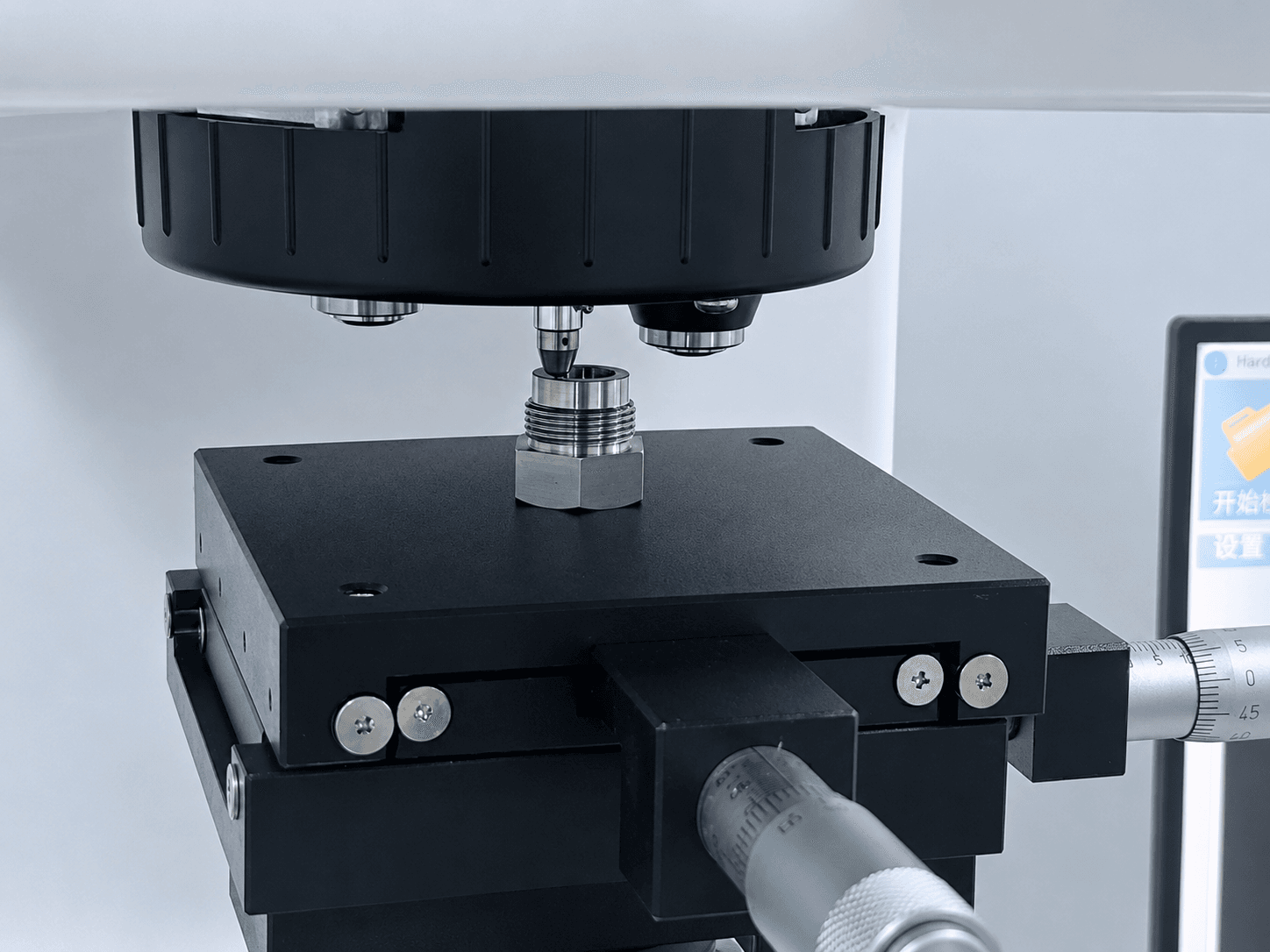
- Hardness and mechanical test reports where specified
This documentation makes incoming inspection at your facility fast and audit-ready.
FAQ
What is the tightest shaft tolerance you can machine?
Ground journal diameters can be held to ±0.002 mm, with runout of 0.005 mm or better, under temperature-controlled conditions. Larger and longer shafts will have slightly relaxed but still tight capabilities.
Do you grind shafts in-house?
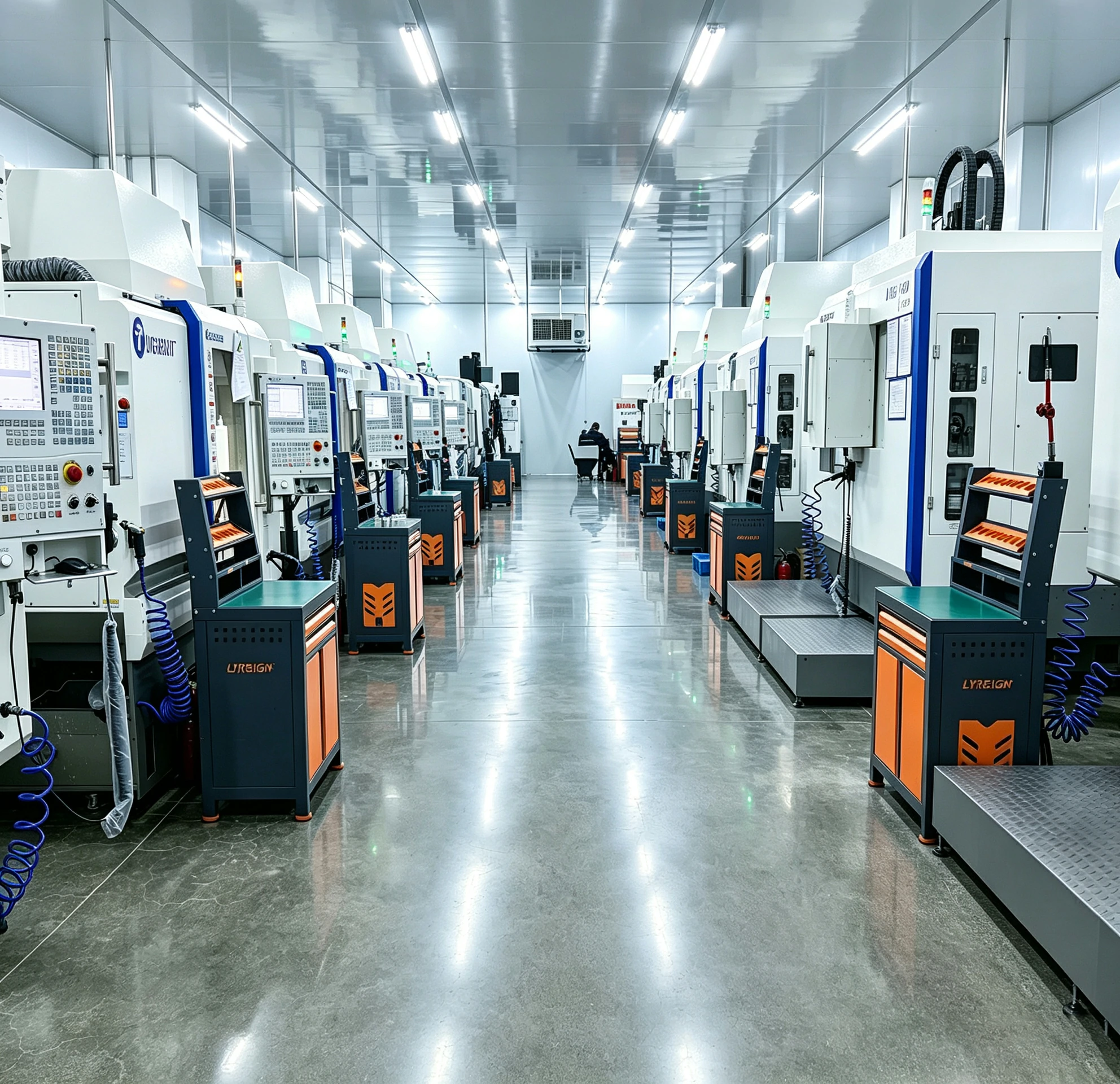
Yes. Precision cylindrical grinding is performed in-house so that turning and grinding stay on one controlled process line.
Can you machine shafts from stainless steel and titanium?
Yes. Stainless, alloy steel, tool steel, and titanium shafts are all standard work for our precision machining line.
Do you supply inspection reports with shaft orders?
Yes. Every shaft order includes a Zeiss CMM inspection report, runout and finish data, and material certificates.
Can you repair or remanufacture worn shafts?
Yes. Worn or damaged shafts can be measured, reverse engineered if needed, and re-manufactured to the original drawing or improved specification.
Upload your shaft CAD drawing for a free DFM review and precision CNC machining quote — including grinding to ±0.002 mm, tight runout control, and full Zeiss CMM inspection reports.