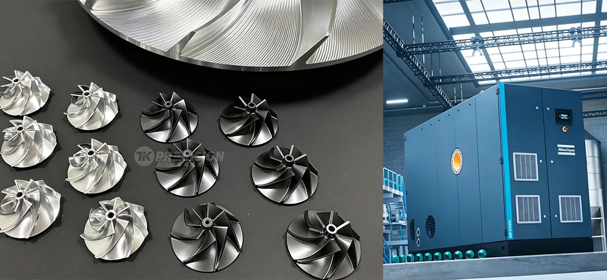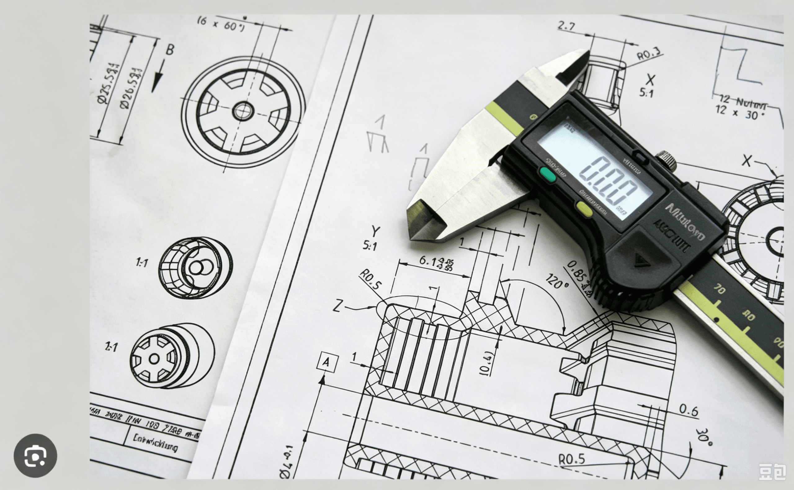
“Machining to print” is the simplest and most reliable way to source precision components: you hold the design, we manufacture exactly what your drawing says, and you receive parts verified against that same drawing. There is no off-the-shelf compromise, no forcing your design to fit a catalog, and no ambiguity about who owns the intellectual property. This model is standard practice for compressor impellers, blades, rotors, shafts, and every other custom machined component.
This article explains how the to-print process works from CAD upload to delivery, what information makes a drawing quote-ready, and how free DFM review plus Zeiss CMM inspection protect your design at every step.
What Does “Machining to Print” Mean?
Machining to print (also called manufacture-to-drawing or custom machining from drawings) means the machine shop produces a part to the customer’s engineering drawing and 3D model. The shop does not modify the design, does not substitute materials, and does not “improve” the geometry without your approval.
In practice, this gives you:
- Full design control — your drawing is the contract
- IP protection — the design remains yours, with NDAs available on request
- One-to-one replication — replacement parts match the original specification exactly
- Traceable quality — every part is inspected against your tolerances, not a generic standard
For OEMs, maintenance teams, and engineering companies, this is the safest procurement path for critical rotating equipment components.
The Machining to Print Process, Step by Step
The workflow from your CAD file to a finished part follows a clear path:
- Upload your CAD drawing — STEP, IGES, SolidWorks, or a 2D PDF with tolerances.
- Free DFM review — engineers analyze the design for manufacturability, cost drivers, and risk.
- Quotation — you receive pricing, lead time, and a clear scope of work.
- Order confirmation — material, process, and inspection requirements are locked in.
- Programming and tooling — CAM programs and fixtures are built from your approved revision.
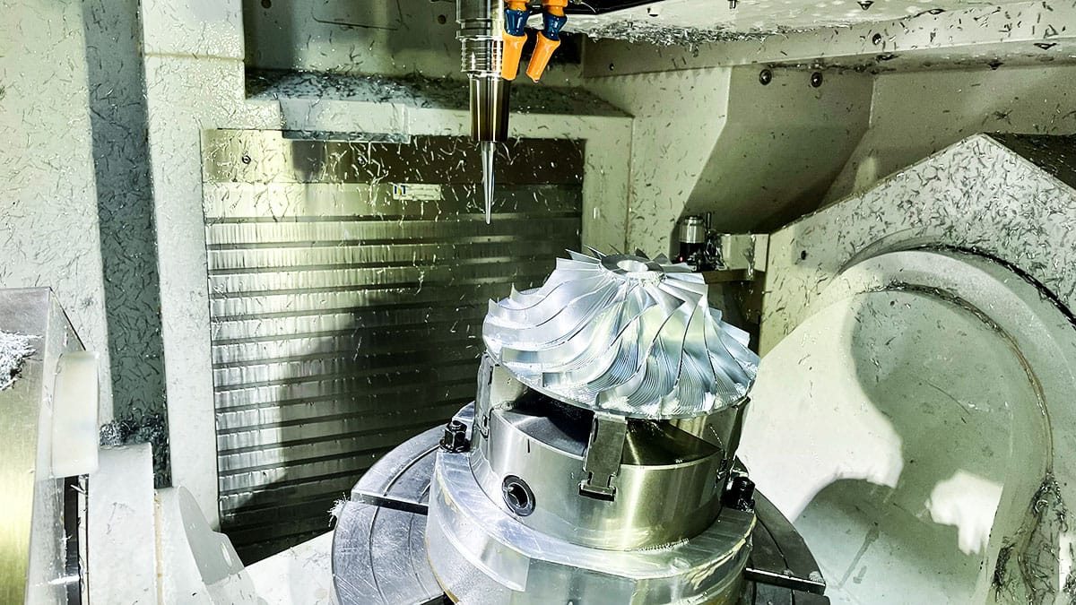
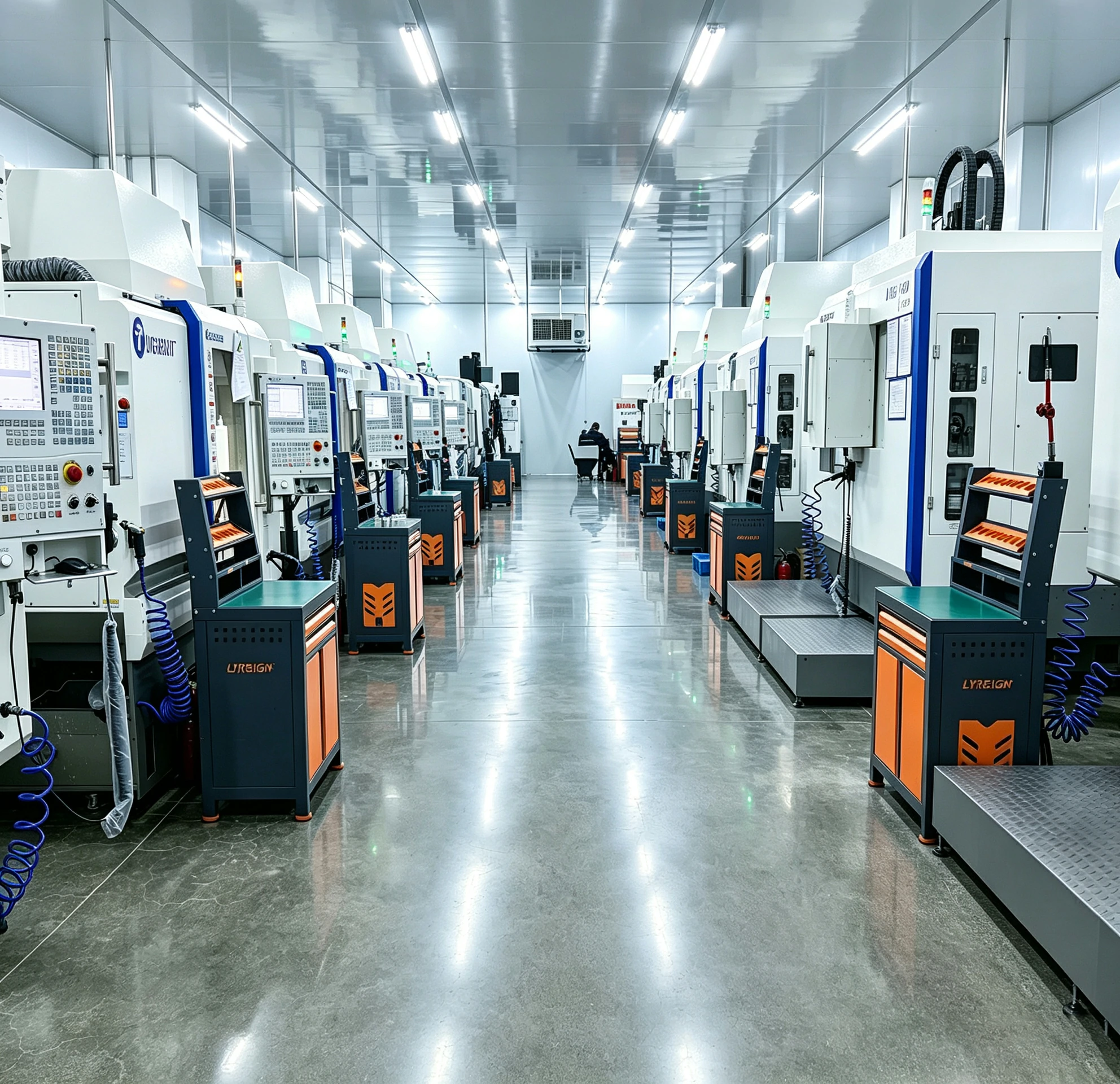
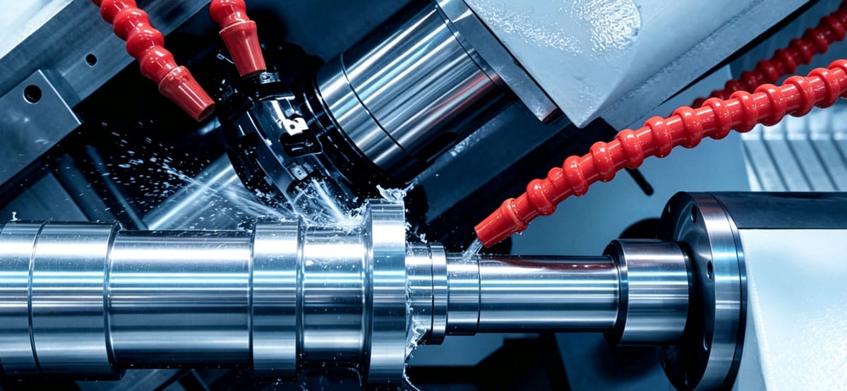
- Machining — turning, milling, grinding, EDM, and finishing are executed to the process plan.
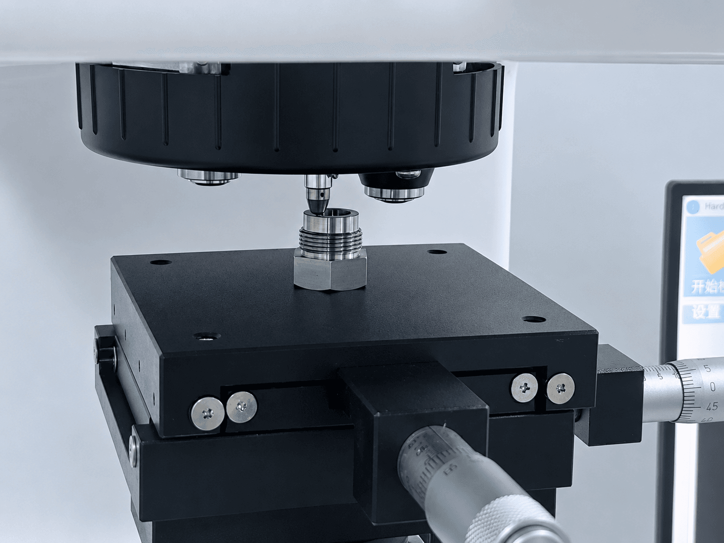
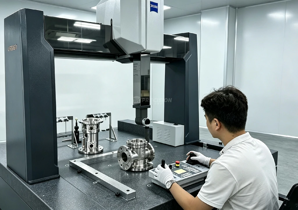
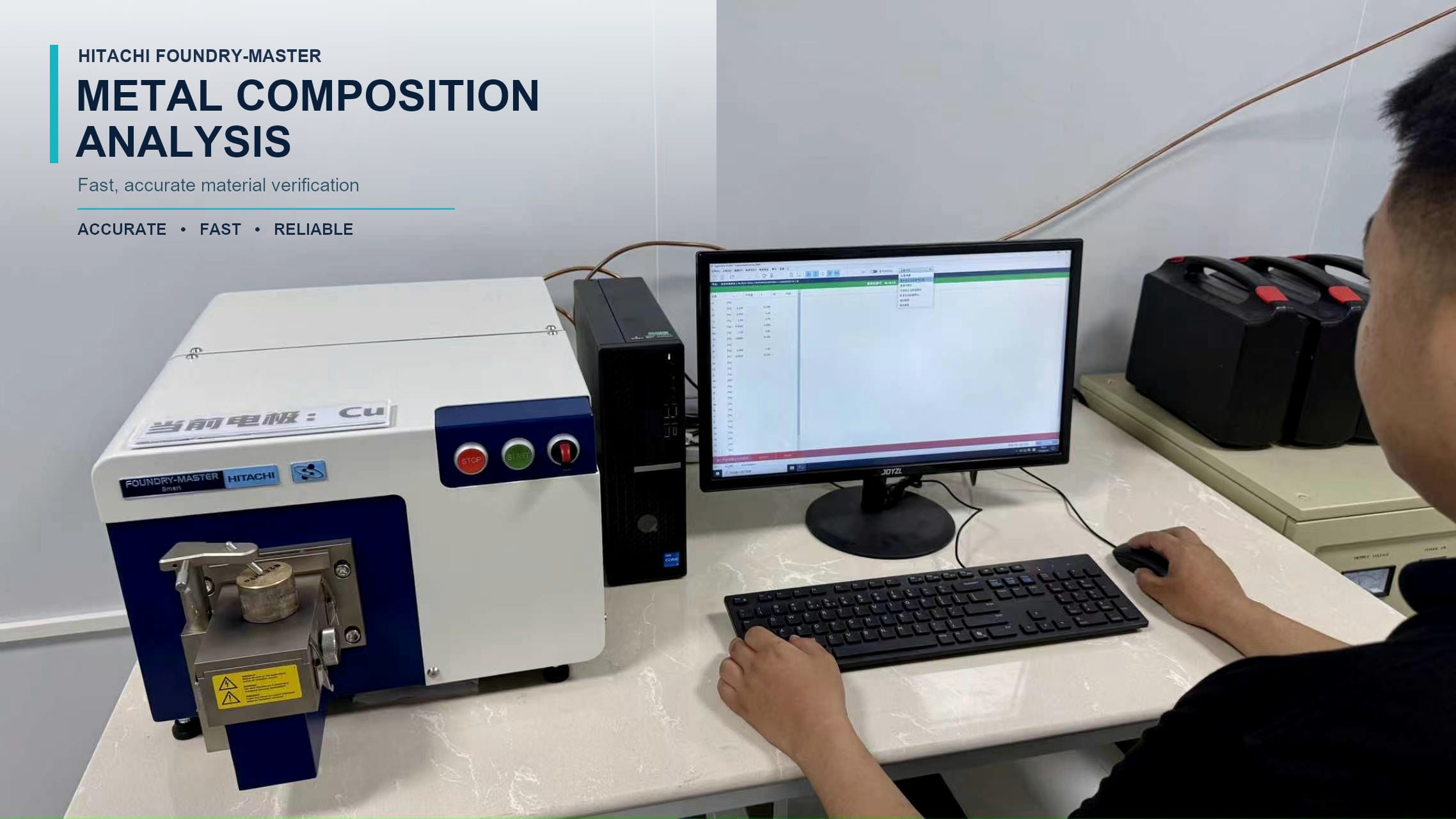
- Inspection — Zeiss CMM measurement verifies every critical dimension against the drawing.
- Documentation and shipping — inspection reports and material certificates ship with the parts.
Because every step is referenced to your drawing, the result is predictable — you know exactly what you will receive before the first chip is cut.
How to Prepare Your CAD Files for a CNC Quote
A good quote starts with a good file package. The most useful submission includes:
| File type | What it provides |
|---|---|
| STEP (.step/.stp) | Reliable 3D solid geometry that works across all CAD platforms |
| 2D PDF or DWG | Tolerances, surface finish, and GD&T callouts that 3D models often omit |
| Material specification | Grade, heat treatment, and hardness requirements |
| Notes on quantity | Prototype vs. production changes cost per part significantly |
| Finish and coating needs | Anodizing, plating, polishing, or coating thickness requirements |
A complete package allows the DFM team to quote once, accurately, instead of sending follow-up questions that delay your project.
Free DFM Review: The Safety Net for To-Print Orders
The free DFM review is what separates professional to-print machining from simple order-taking. Before committing to production, the engineering team checks your drawing for:
- Features that cannot be machined with standard tooling
- Tolerances that are tighter than necessary (and therefore expensive)
- Fixturing and clamping strategies for the geometry
- Material and heat treatment compatibility with the specified tolerances
- Inspection method feasibility for each critical dimension
The DFM feedback is yours to use — whether you approve the design as-is or adjust the drawing to save cost. Either way, you make the final decision.
Protecting Your Design: IP and Confidentiality
For custom machined components, design ownership is non-negotiable. On request, we work under NDA, restrict file access to the project team, and delete engineering data after order completion. Your drawing stays yours; the shop simply executes it.
Reverse Engineering as a Path to To-Print Machining
Sometimes the drawing no longer exists. For legacy compressor components, worn parts can be measured on a Zeiss CMM, reconstructed as a solid model, and re-manufactured to the original geometry — or improved where reliability requires it. This “reverse to print” service covers:
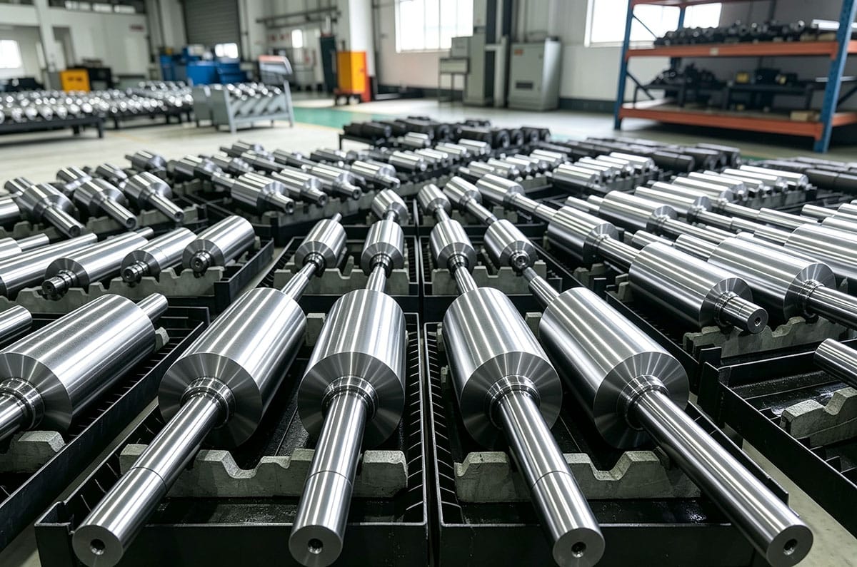
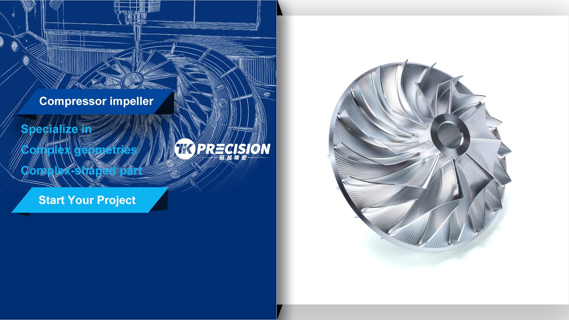
- Impellers and blades with worn or damaged airfoils
- Rotors and shafts needing replacement without original drawings
- Couplings, spacers, and seals for legacy machines
- Modified designs with enhanced materials or coatings
Why Choose To-Print Machining for Compressor Components?
Compressor parts operate at high speed under load, so design integrity is everything. Machining to print means:
- No functional surprises — the part matches the geometry your engineers validated
- Consistent replacement parts — identical geometry, material, and balance characteristics
- Auditable quality — dimensional reports reference the same drawing your design team uses
- Shorter procurement cycles — once the DFM and quote are approved, production starts immediately
Whether you need one critical impeller or a production run of rotor shafts, to-print machining keeps your design in control.
FAQ
What CAD file formats do you accept for to-print machining?
STEP (.step/.stp), IGES, SolidWorks native files, and 2D PDF/DWG drawings are all accepted. STEP is preferred because it preserves solid geometry across platforms.
Can you machine to print if I only have a PDF drawing, not a 3D model?
Yes. A dimensioned 2D drawing is sufficient for many parts. For complex freeform geometry, the team may rebuild the 3D model from the drawing and confirm it with you before production.
Do you sign NDAs for custom parts?
Yes. Non-disclosure agreements are available and commonly used for custom compressor component projects.
How do I get a quote for machining to print?
Upload your CAD files through the website or email them to the engineering team. You will receive free DFM feedback and a quotation, normally within one business day.
What tolerances can you hold on to-print parts?
Critical ground features can be held to ±0.002 mm, with runout and roundness controlled to microns. Freeform profiles such as impeller airfoils are held to ±0.01–0.02 mm in production.
Upload your CAD drawing today for free DFM feedback and a machining-to-print quotation — every part is manufactured to your design and verified with full Zeiss CMM inspection.