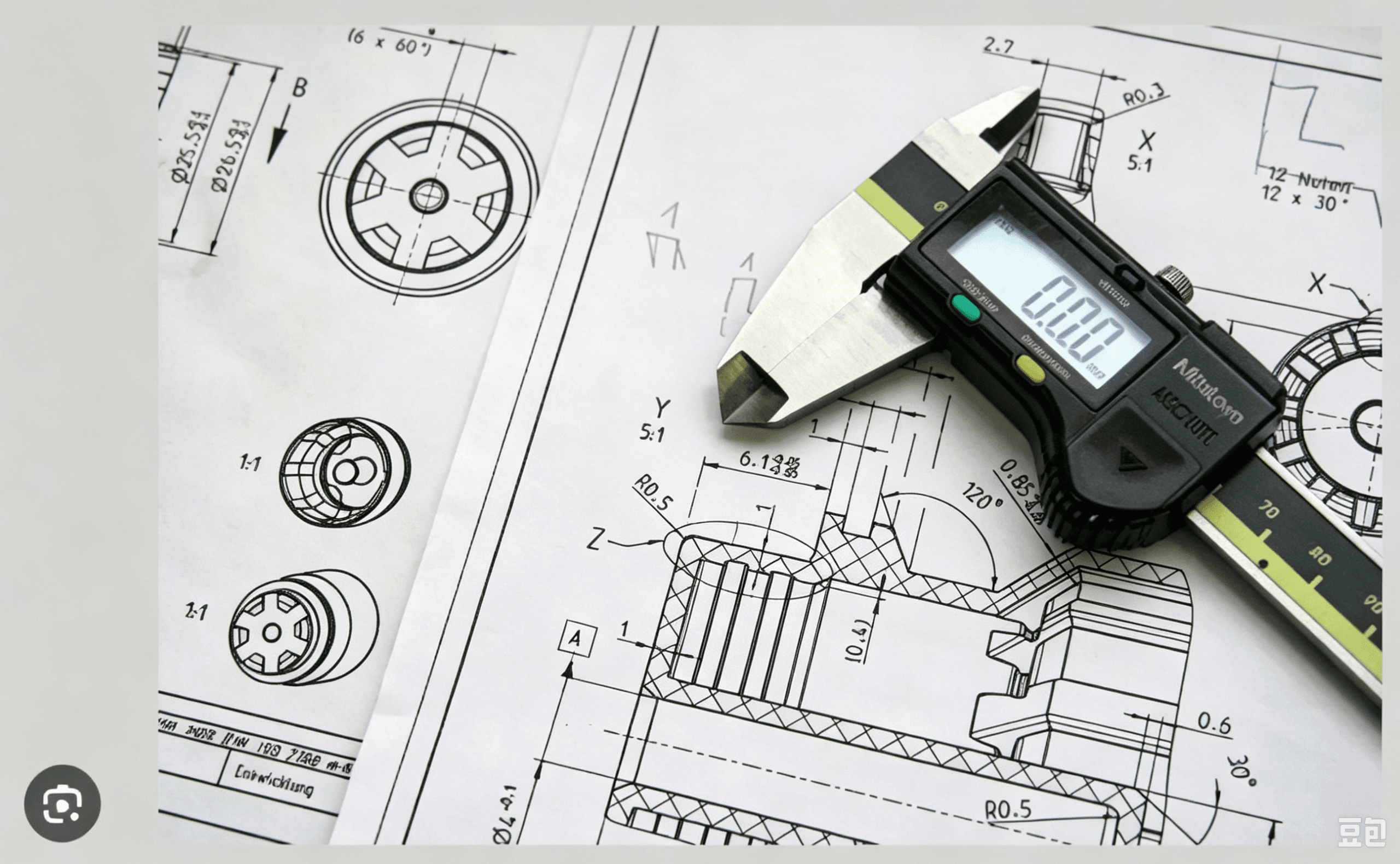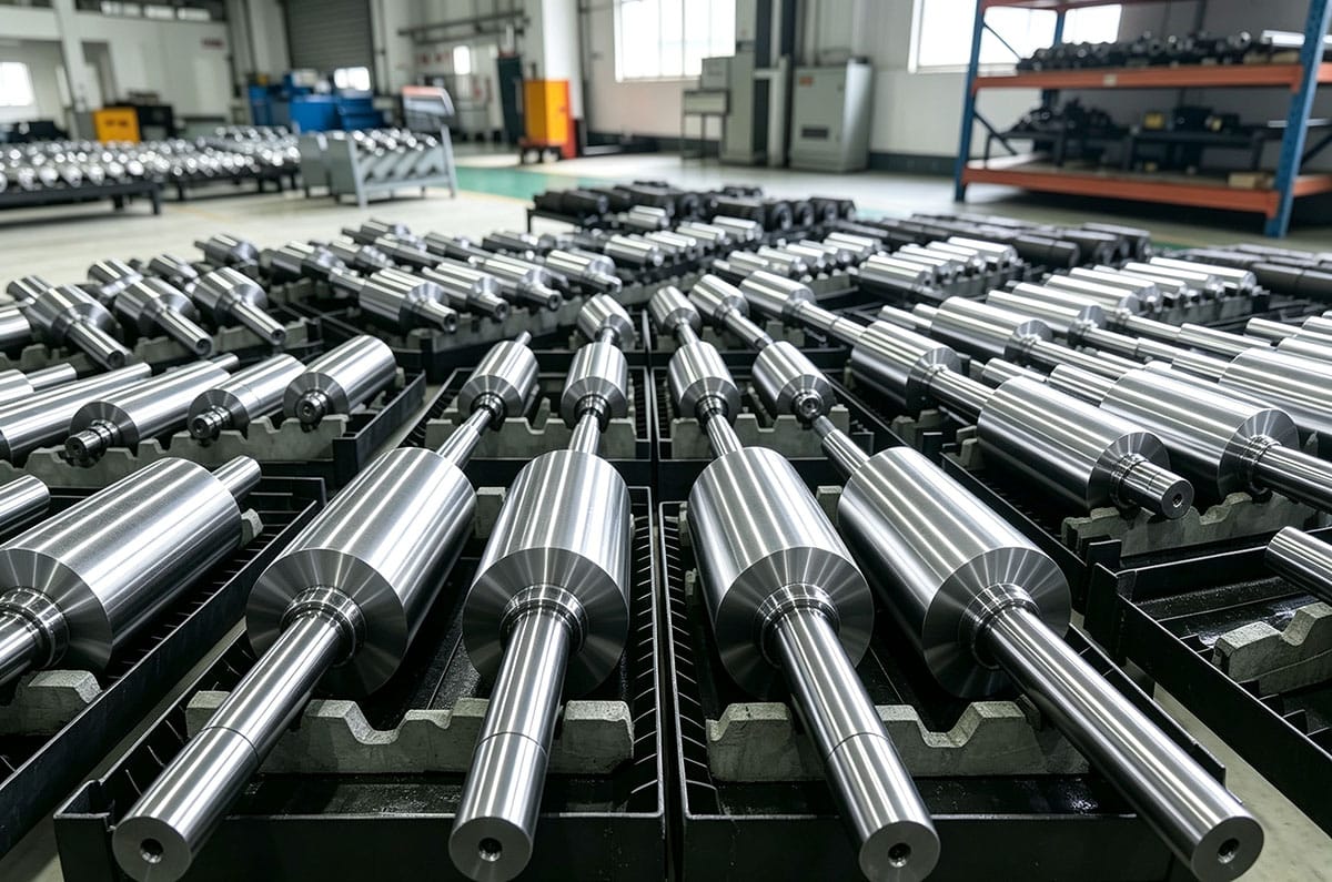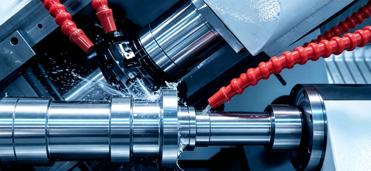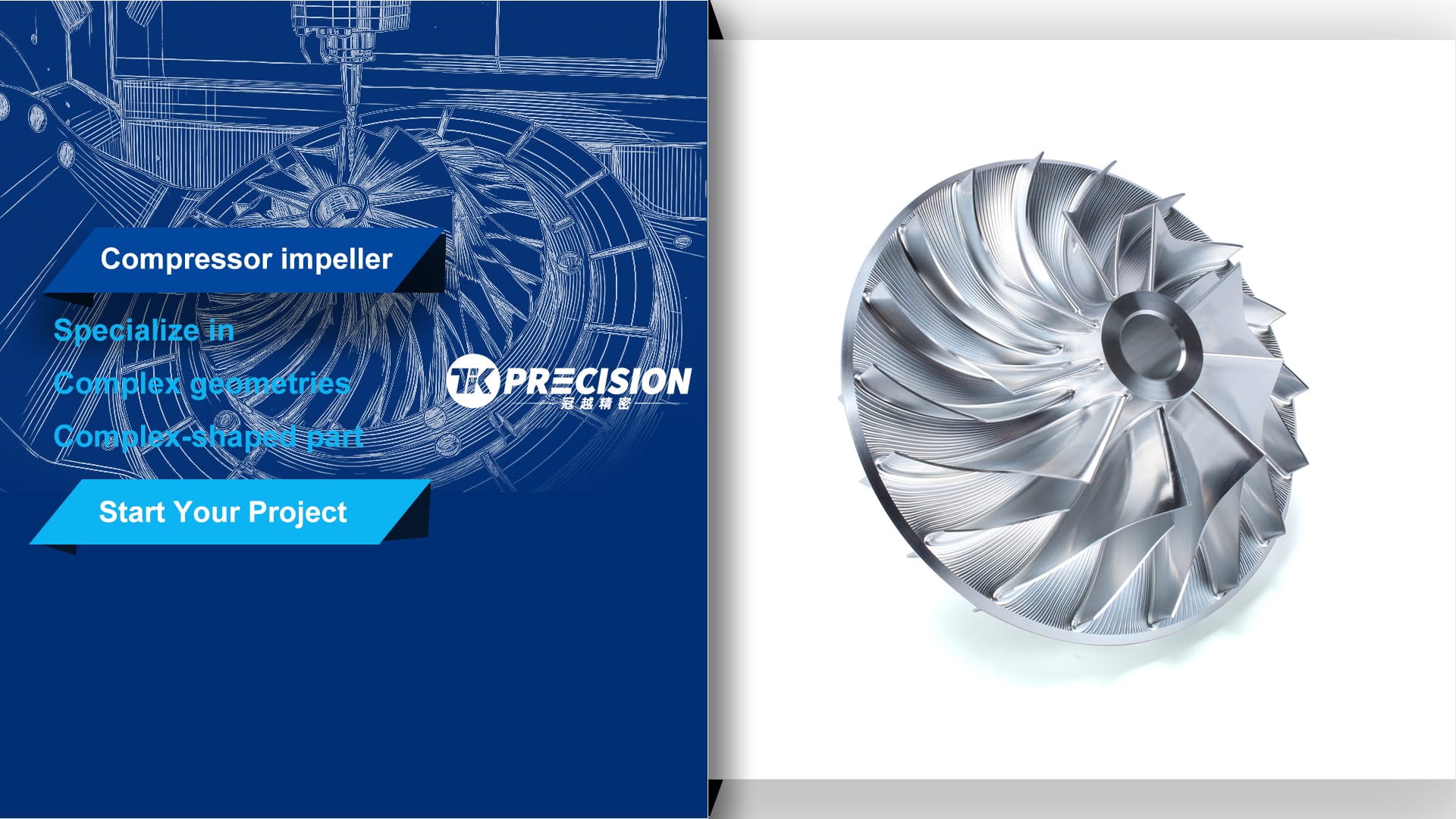
“±0.002 mm” — or 2 microns — appears on engineering drawings for high-performance components such as compressor impellers, rotor journals, seal diameters, and precision shafts. It is one of the tightest tolerances used in production machining. This guide explains what 0.002 mm means, where it can be held, and how it is verified. For related applications, see our guide to precision CNC machining for compressor components.
What Is 0.002 mm?
0.002 mm equals 2 micrometers (µm), or approximately 0.00008 inches. A human hair is roughly 0.06–0.1 mm thick, making it 30 to 50 times larger than this tolerance band. At this scale, measurement becomes part of the engineering problem.
Which Features Can Hold ±0.002 mm?
| Feature type | Can ±0.002 mm be held? | Typical production value |
|---|---|---|
| Ground journal diameters | Yes | ±0.002–0.005 mm |
| Precision bores | Yes | ±0.002–0.005 mm |
| Seal and bearing seats | Yes | ±0.003–0.008 mm |
| Small, rigid turned diameters | Sometimes | ±0.005–0.01 mm |
| Long shafts and thin walls | Rarely | ±0.01 mm or more |
| Freeform blade surfaces | No | ±0.01–0.02 mm |
Small, rigid, ground features hold micron tolerances more reliably than large, flexible, or freeform features.
What It Takes to Hold 2 Microns
- Temperature control — thermal expansion can consume the entire tolerance band.
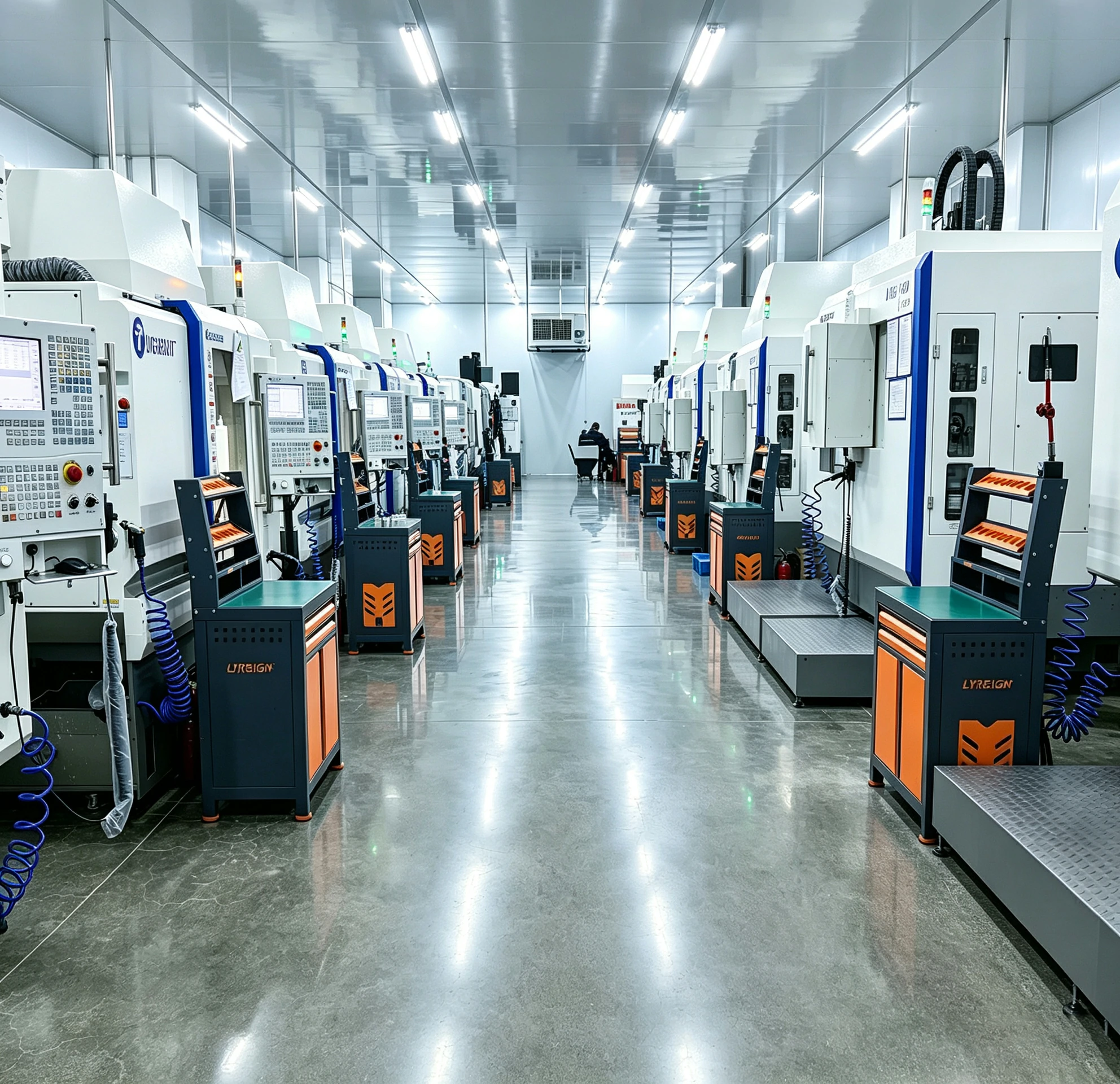
- Precision grinding — tight diameters are usually ground rather than turned.
- Machine condition — spindles, slides, and probes require regular calibration.
- Rigid tooling and fixtures — cutting-force deflection must be controlled.
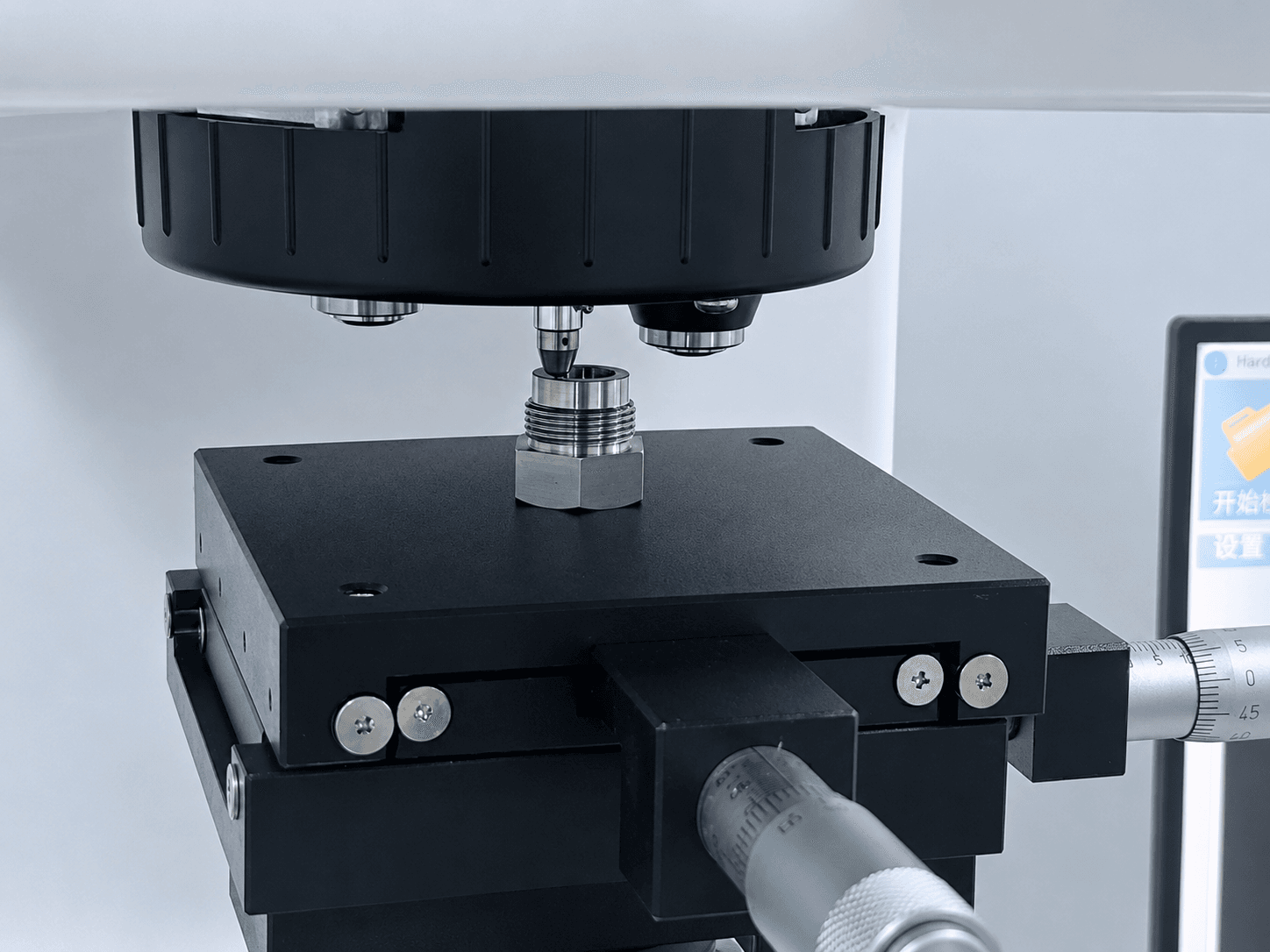
- Measurement capability — the CMM or gauge must be significantly more accurate than the tolerance being measured.
How ±0.002 mm Is Verified
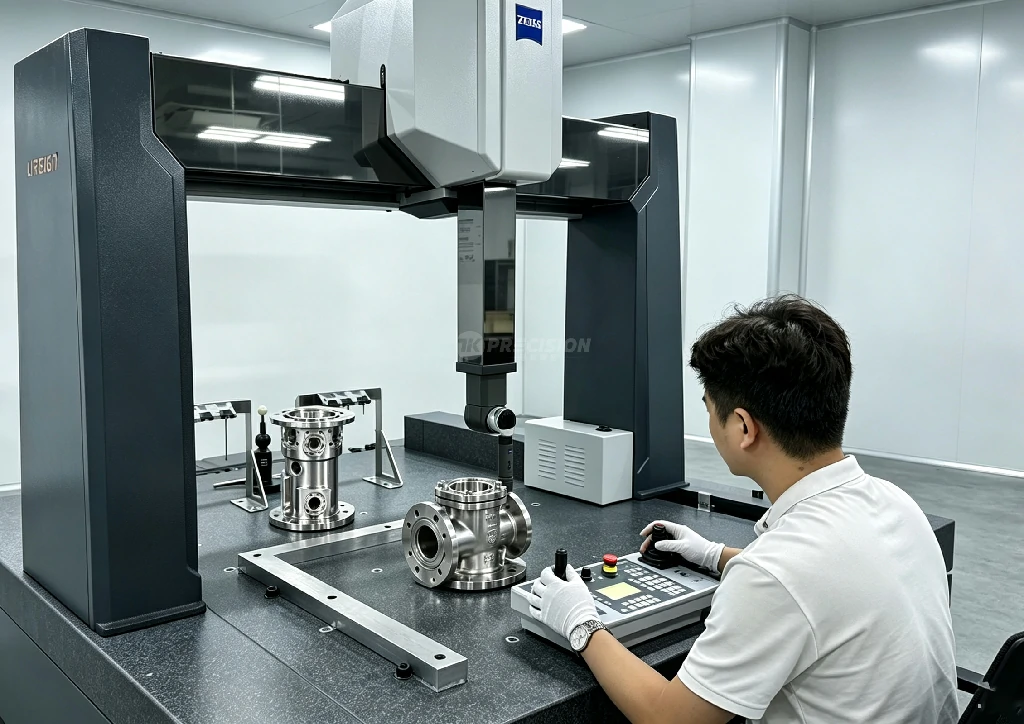
A tolerance is only meaningful when measurement uncertainty is controlled. Zeiss CMM equipment supports low-uncertainty measurement of diameters, positions, and profiles through calibrated probing, scanning, temperature compensation, and repeatability studies.
- Zeiss CMM measurement for critical dimensions and profiles
- Multiple-point probing and scanning to reduce measurement error
- Temperature-controlled inspection to limit thermal drift
- R&R studies to confirm repeatability and reproducibility
How to Specify Tight Tolerances
- Tighten only functional features such as bearing seats, seal diameters, and mating fits.
- Use GD&T for runout, roundness, and cylindricity when required by function.
- Reference the correct datums.
- Request a DFM review to identify unnecessarily expensive tolerances.
A part with four tight features generally costs far less than one with forty.
Applying ±0.002 mm Capability
- Compressor rotor journals ground to ±0.002 mm with controlled runout
- Impeller bores and seal seats precision-ground and CMM-verified
- Precision shaft diameters ground to drawing requirements with documentation
- Fixture and gauge components manufactured to the same precision discipline
Critical features are verified on Zeiss CMM equipment, with inspection documentation supplied with the parts.
FAQ
Is ±0.002 mm achievable in CNC machining?
Yes, on suitable small, rigid, ground diameters and bores under controlled conditions. Large, flexible, or freeform surfaces require different tolerances.
What is 0.002 mm in inches?
Approximately 0.00008 inches.
Why do tight tolerances cost more?
They require grinding, temperature control, premium tooling, slower cycles, and CMM verification.
Should I put ±0.002 mm on every dimension?
No. Apply tight tolerances only where function requires them and use DFM feedback to identify the critical features.
Upload your drawing for a free DFM review and a quotation stating which features can hold ±0.002 mm, verified by Zeiss CMM inspection.