
Compressor components are among the most demanding parts in precision manufacturing. Rotors spin at tens of thousands of revolutions per minute, gas-path surfaces are machined to aerodynamic profiles, and a single unbalanced impeller can create vibration that shortens bearing life across the entire machine. For engineers and purchasing teams sourcing compressor parts, understanding what precision machining can — and cannot — control is often the difference between a smooth project and a costly rework loop.
This guide covers the compressor parts most commonly machined, the materials and processes that make them work, the balancing and inspection standards that matter, and what to prepare before requesting a quote.
Why Compressor Parts Demand Precision Machining
Three characteristics put compressor components in a different class from ordinary machine parts:
- Tight tolerances. Rotating and sealing surfaces frequently require tolerances in the 0.002–0.02 mm range. Once material is removed, an aerodynamic profile cannot be corrected later.
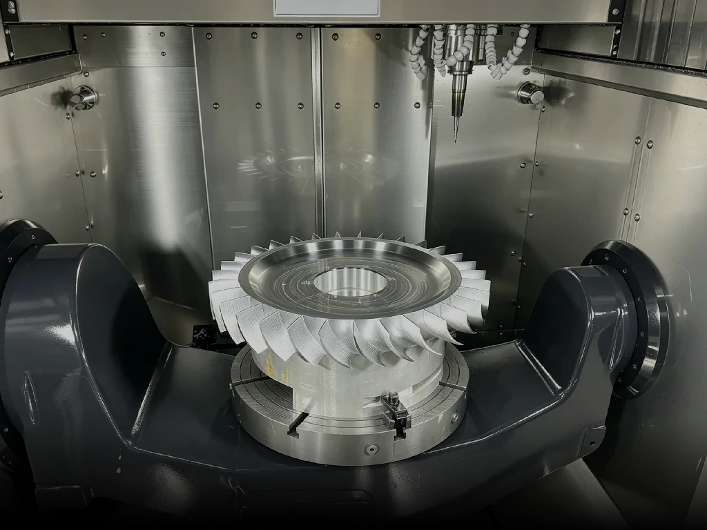
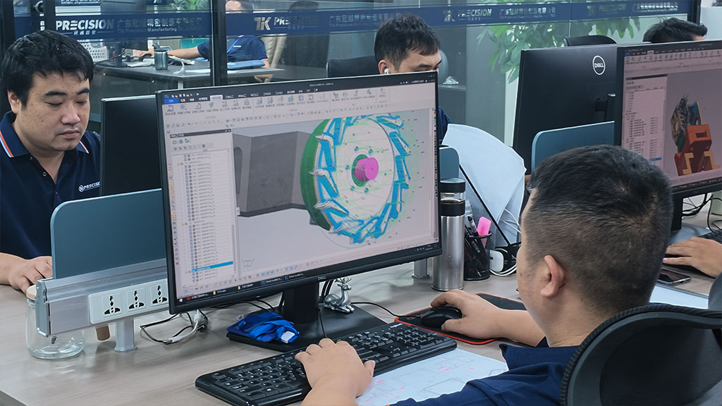
- Complex geometry. Twisted blades, thin walls, deep channels and undercuts push the limits of standard 3-axis work and require simultaneous 5-axis machining.
- Difficult materials. High-strength alloys used at high temperatures are among the hardest materials to machine consistently.
Compressor Parts We Machine
Compressor designs vary by type, but the components that need precision machining fall into a few families:
- Centrifugal compressors: open and shrouded impellers, diffusers, volutes and housings, balance pistons, and sealing components.
- Reciprocating compressors: pistons, cylinders, valve plates and crossheads.
- Screw compressors: rotors and rotor housings.
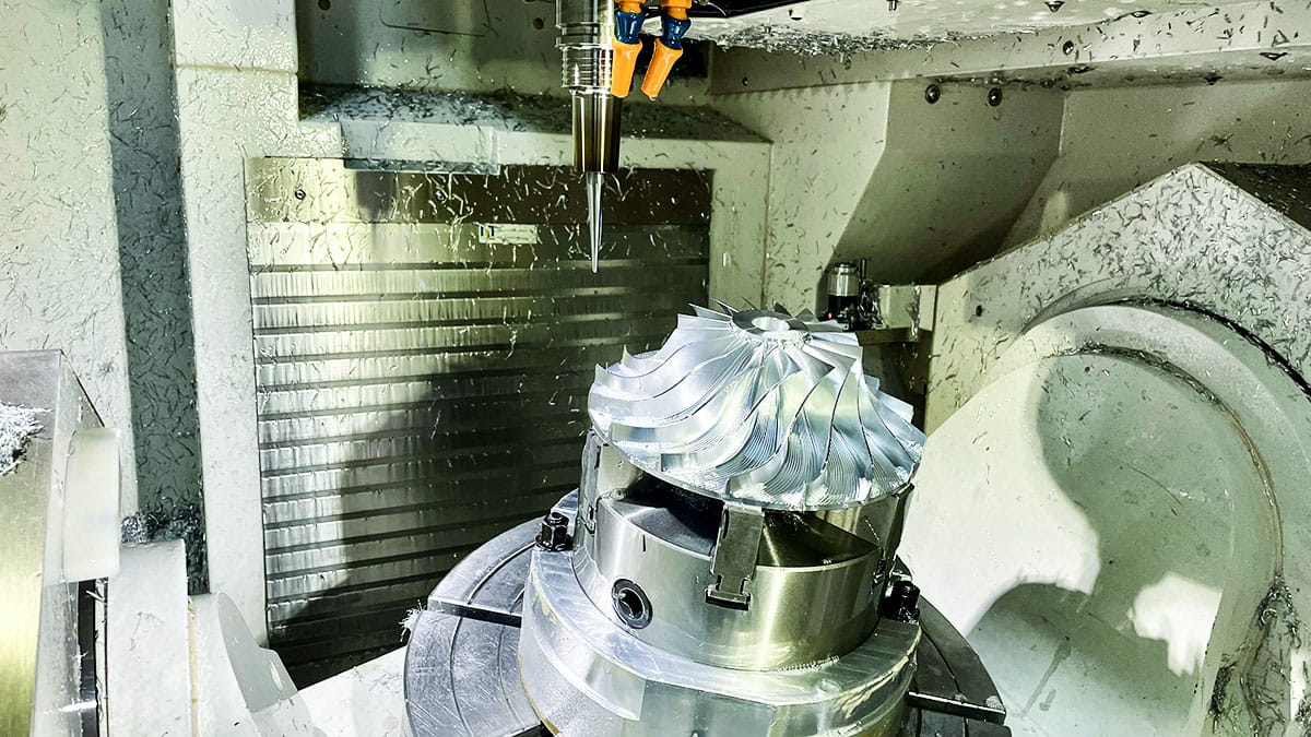
Impellers deserve special attention because blade geometry, surface finish and balance all affect aerodynamic performance directly. For a deeper look at impeller-specific tooling and programming, see our guide on 5-axis impeller CNC machining for turbomachinery.
Material Selection Matters
The right material defines cutting strategy, tooling and cost. The table below summarizes the materials most often used in compressor components:
| Material | Typical components | Machining notes |
|---|---|---|
| Aluminum (6061, 7075) | Turbocharger wheels, lightweight housings | Fast machining, excellent finish, anodizable; high strength-to-weight ratio. |
| Stainless steel (304, 316L, 17-4PH) | Housings, shafts, valve components | Work-hardens; feeds must stay above the work-hardening threshold. |
| Titanium (Ti-6Al-4V) | Aerospace and high-speed impellers | Strong and light, but low thermal conductivity keeps heat in the tool — slower speeds, rigid setups. |
| Nickel alloys (Inconel 718, Hastelloy) | High-temperature impellers, diffusers | Work-hardens immediately with extreme tool wear; requires coated tooling and high-pressure coolant. |
Machining Processes for Compressor Components
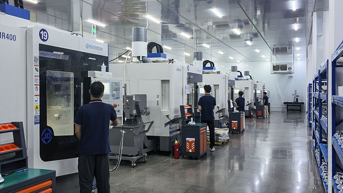
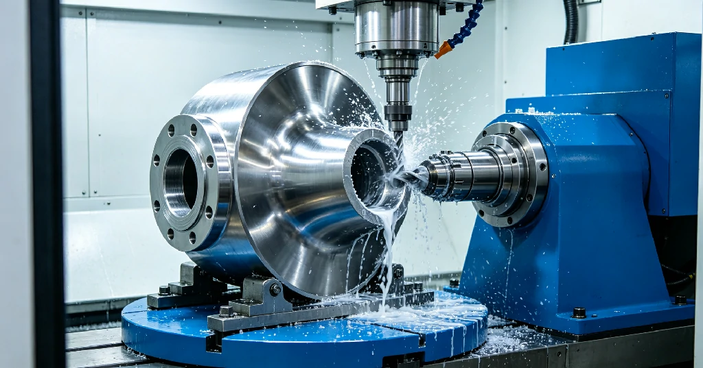
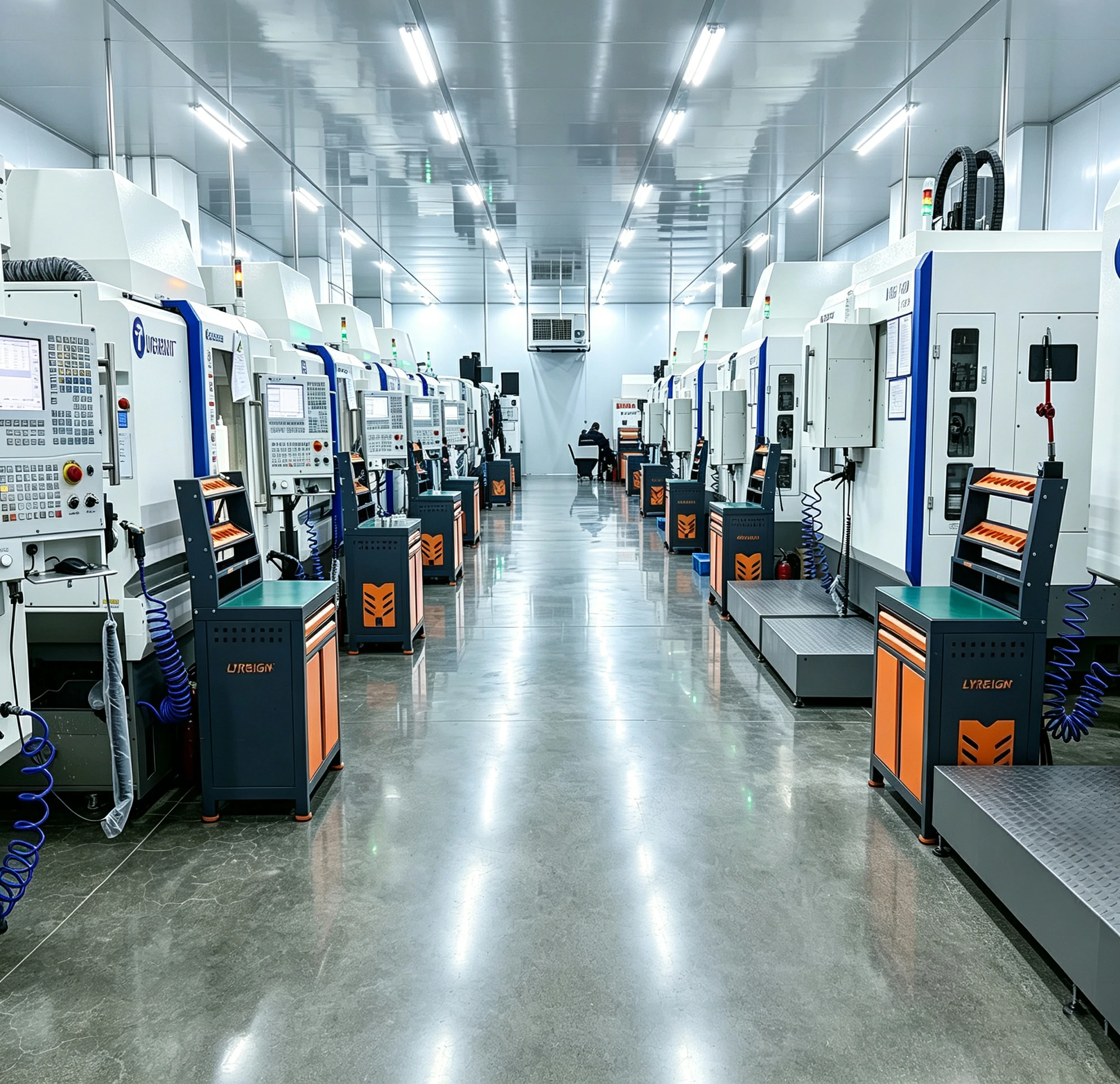
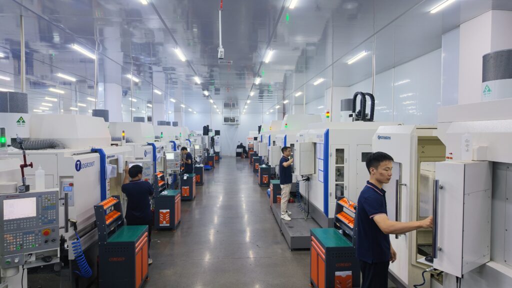
- 5-axis CNC milling. The core process for impellers and bladed parts. Tapered ball-nose end mills follow the blade channel in roughing, semi-finishing and finishing passes, so geometry, twist and surface finish are cut in one setup.
- Mill-turn. For shafts and stepped rotors, combined milling and turning in one setup reduces datum error and lead time.
- EDM. For shrouded or closed impellers where a cutter cannot reach, wire or sinker EDM finishes the internal channels.
- Dynamic balancing. Rotating parts are balanced to ISO 1940-1 (ISO 21940-11) quality grades. G2.5 is the typical grade for compressors and high-speed rotors; balancing allowance is left on the correction planes during machining.
- Surface treatment. Anodizing, coatings and other finishes are applied after machining, according to service conditions.
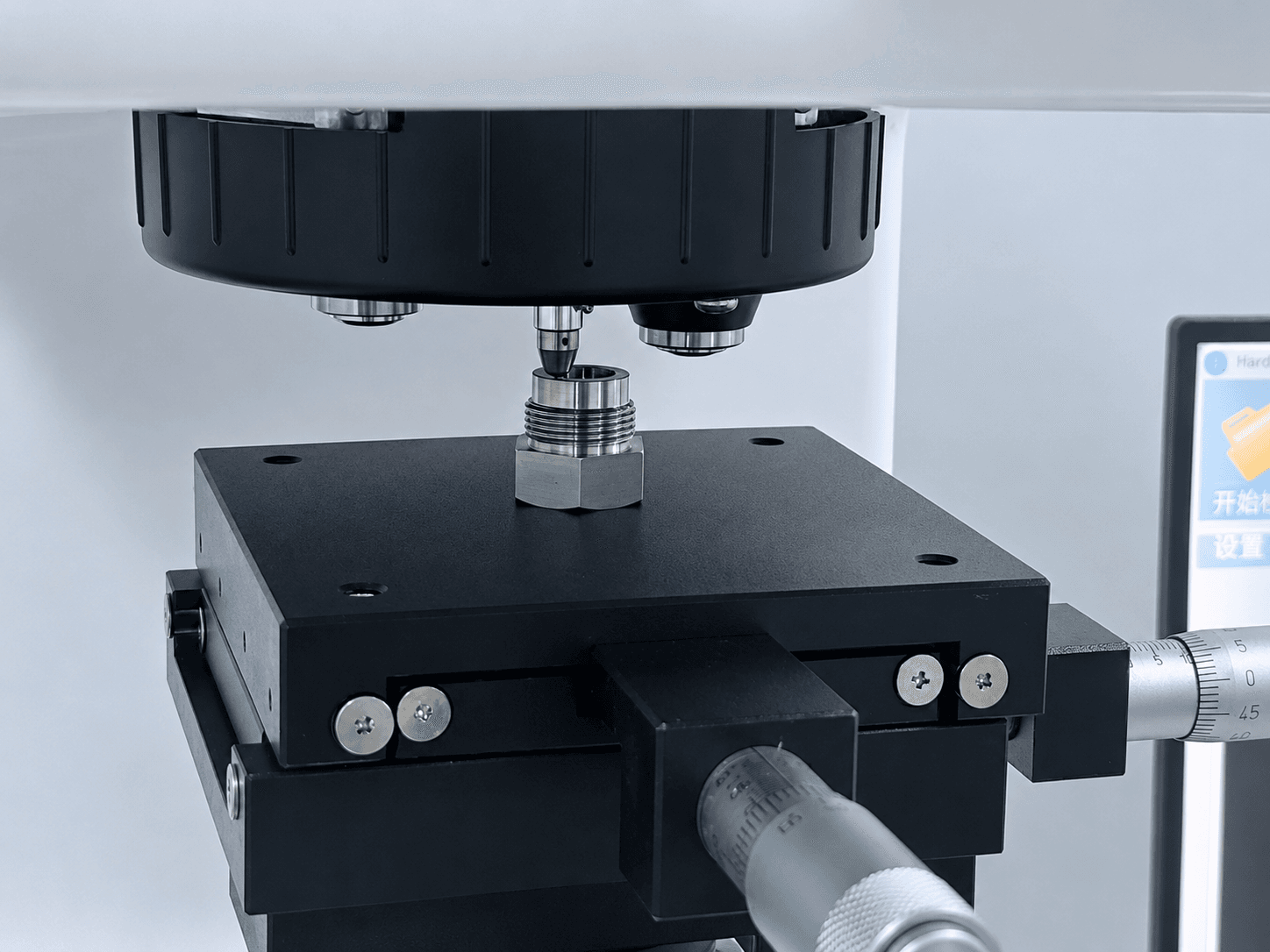
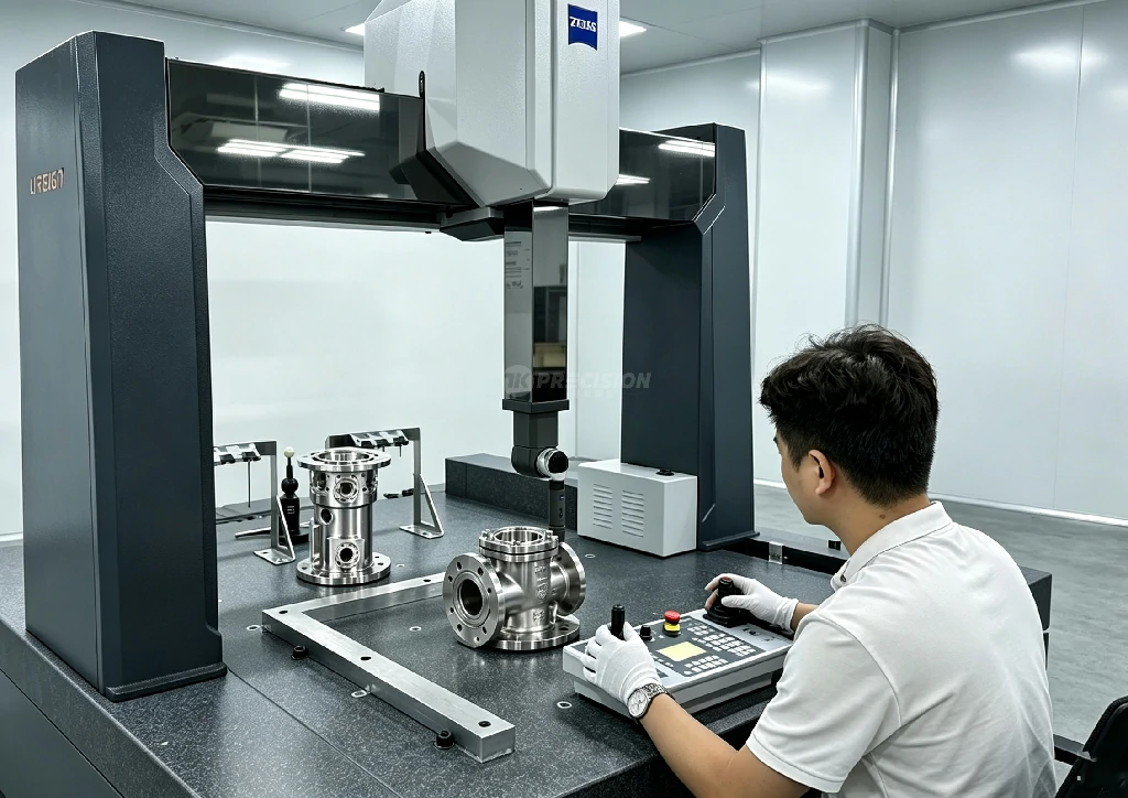
- Inspection. Full-dimensional verification on CMM, plus surface roughness measurement, before shipment.
Design for Machinability: Five Practical Tips
- Use a DFM review early. A free design-for-manufacturability analysis before production catches geometry, tool-access and tolerance issues while changes are still cheap.
- Specify achievable tolerances. Our practical capability holds tolerances to 0.002 mm. Specify what the function requires — tighter tolerances increase cost everywhere.
- Define a clean datum structure. Machining datums should match assembly datums so critical fits are controlled directly.
- Leave balancing allowance. Rotors need stock on correction planes for dynamic balancing after machining.
- Set realistic surface finishes. Functional sealing and aerodynamic surfaces typically need Ra 0.4–1.6 µm; specify finish only where it matters.
Quality Verification
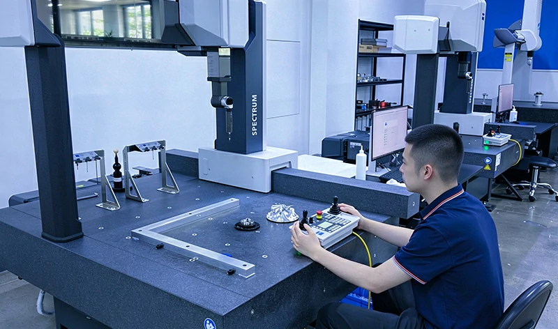
Compressor parts ship with evidence, not just promises. Our quality system is certified to ISO 9001 and GJB 9001, and every batch passes 100% CMM inspection on ZEISS machines, with inspection reports provided with each shipment.
Requesting a Quote: What to Prepare
To get an accurate quote quickly, prepare:
- CAD files in STEP/STP, SLDPRT, IPT, PRT or SAT format;
- callouts for critical tolerances and surface finish;
- quantity and expected delivery date.
We provide free DFM analysis, quotes within 2 hours, typical lead times from 3–7 days, and no minimum order quantity — so prototypes and low-volume production start without friction.
Ready to discuss your compressor components? Upload your CAD files for a free DFM analysis and quote.