

Why blade dimensions barely differ across manufacturers
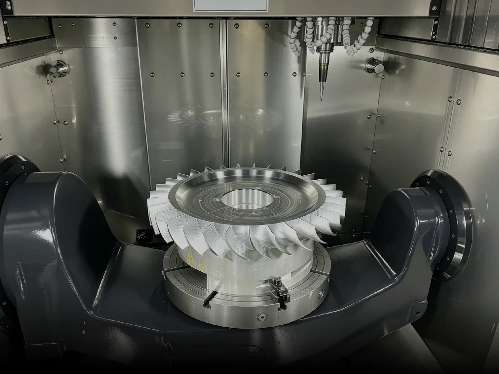
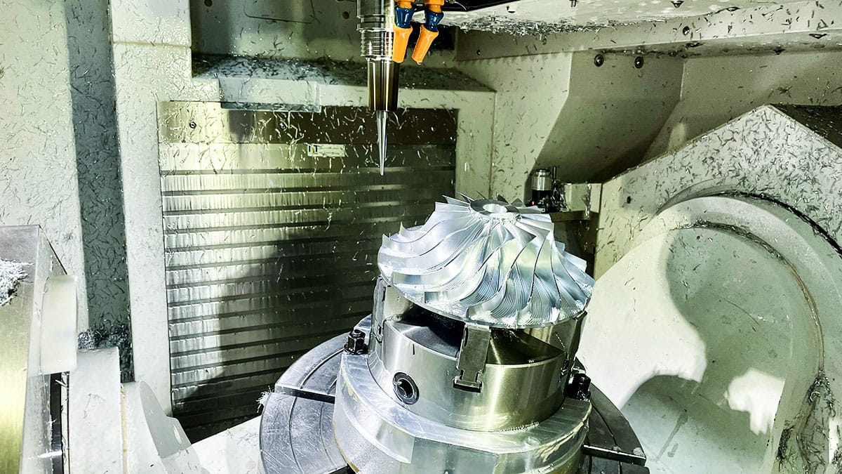
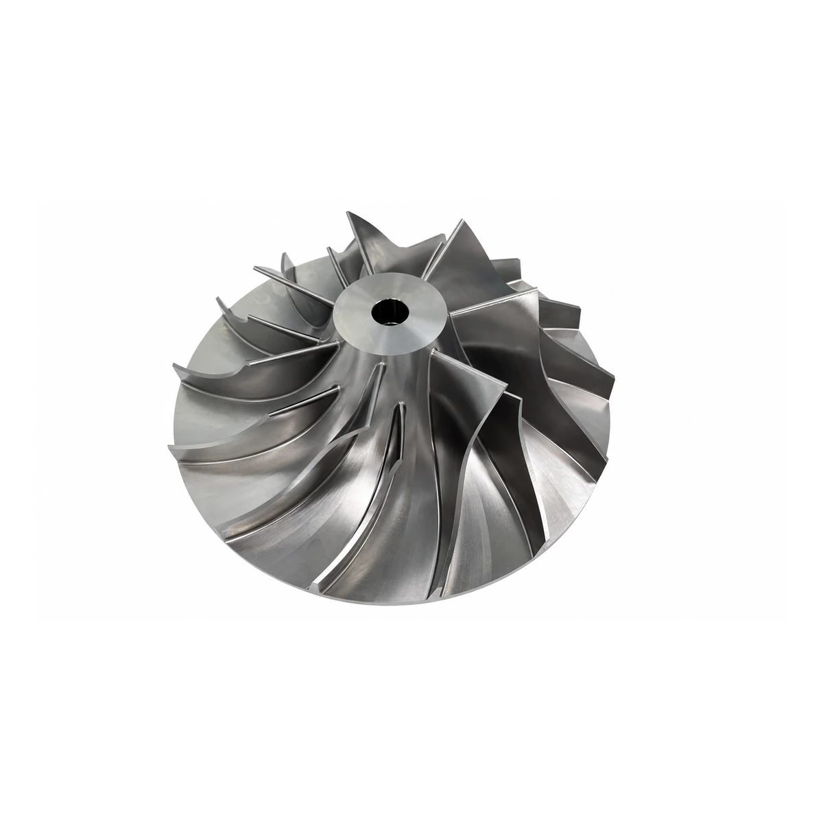
This impeller is a monolithic 6061‑T6 aluminum piece manufactured by CNC machining. It has an outer diameter of 28.8 mm and runs on a high‑speed motor at 100,000 RPM.
This article focuses on one task only: centrifugal strength verification. Aerodynamic pressure and balancing are excluded. We lock the rotational speed and calculate how much stress the centrifugal inertia force generates inside the part.
Figure 1: 3D model of the 6061‑T6 monolithic machined impeller

Conclusion upfront
Under pure centrifugal loading, the maximum von Mises stress reaches 48.56 MPa.
Against the yield strength of 6061‑T6 (276 MPa), the safety factor is 5.7.
Against fatigue strength (~96 MPa), the safety factor is 2.0.
Back‑calculated limit speeds: approximately 140,000 RPM to hit the fatigue threshold, and roughly 240,000 RPM to reach yield.
Strength margin is sufficient; centrifugal strength is not the bottleneck of this impeller.
Rotational speed, material selection and blade balancing collectively constrain the blade diameter.

1:Fixed boundary conditions
| Item | Value |
|---|---|
| Material | 6061‑T6 aluminum alloy, monolithic CNC machined |
| Impeller outer diameter | 28.8 mm |
| Rotational speed | 100,000 rpm |
| Angular velocity | 10,472 rad/s |
| Load case | Centrifugal inertia force only; no aerodynamic pressure |
| Temperature | Ambient temperature; no strength derating for temperature rise |
Tip speed for a 28.8 mm OD impeller at 100,000 RPM:

That equals about 543 km/h. This value will be reused below.
2:Hand calculation: establish a stress range
Hand calculations serve two purposes before simulation: to estimate the expected magnitude and cross‑validate whether the simulation result is reasonable.
Method 1: Tip speed approximation
Treat all mass as concentrated on a thin ring at the tip radius. Hoop stress for a rotating ring:

This method overestimates stress because all mass is assumed to sit at the maximum radius. It acts only as an upper bound.
Method 2: Rotating disk with central bore The impeller approximates a rotating disk with a central hole. For a uniform‑thickness rotating disk, stress scales with For a solid disk, maximum hoop stress occurs at the center:
With a central bore, stress concentrates at the inner edge of the hole. Hoop stress at the bore:
Hand calculation yields a range of 52 ~ 61 MPa. These formulas assume uniform thickness, no blades and no hub constraint. They are for range estimation only, not final conclusions.
3. Flexible‑body coupling simulation: true stress field
An impeller is not rigid. Rigid body dynamics can compute reaction forces and displacements but cannot resolve stress. To obtain the stress field, the component must be defined as deformable. We convert the impeller into a flexible body using modal superposition. Centrifugal inertia loads are distributed over the real geometry before solving for stress. This case uses Adams for flexible‑body coupling simulation under pure centrifugal load, aerodynamic pressure excluded. Result: maximum von Mises stress = 48.56 MPa
Figure 2: Von Mises stress contour of the impeller under pure centrifugal load
The hand‑calculated bore stress was 52.4 MPa; simulation returns 48.56 MPa, a difference of 7%. The gap is expected because the analytical formula ignores blades, hub boundary conditions and fillet radii at the bore. The model is validated.
Two sources contribute to the stress distribution:
- Hoop tensile stress in the disk generated by centrifugal pulling
- Bending stress at blade roots from the centrifugal mass of each blade
According to rotating disk theory, peak hoop stress in the disk appears at the inner bore edge. Peak stress at blade roots is heavily influenced by transition fillets. The location of maximum stress is shown on the contour plot above.
4. What does 48.56 MPa mean?

| Criterion | 6061‑T6 Value | Safety Factor |
|---|---|---|
| Yield strength | 276 MPa | 5.7 |
| Ultimate tensile strength | 310 MPa | 6.4 |
| Fatigue strength (\(5\times10^8\) cycles) | ~96 MPa | 2.0 |
Fatigue must be considered: 100,000 RPM equals 1667 rotations per second. One hour of operation creates 6 million cycles. One full day creates 140 million cycles. Static yielding does not guarantee safety at such high cycle counts.
Why \(5\times10^8\) cycles? Aluminum alloys do not possess a true fatigue limit. Their S‑N curves keep declining without a horizontal asymptote. We must define a target cycle count and use the corresponding fatigue strength. For 6061‑T6, this value is approximately 96 MPa at \(5\times10^8\) cycles.
Limit speed derivation: stress scales with the square of rotational speed
- Fatigue threshold (96 MPa): \(100000 \times \sqrt{96 / 48.56} \approx 141,000\ \text{RPM}\)
- Yield threshold (276 MPa): \(100000 \times \sqrt{276 / 48.56} \approx 238,000\ \text{RPM}\)
From centrifugal strength alone, this impeller retains more than double the rotational speed margin.
5. Boundary assumptions of this result
The 48.56 MPa result is valid only under pure centrifugal loading. Any citation must include these limits:
- Aerodynamic pressure excluded: real working conditions impose pressure difference across blades, adding bending stress on top of centrifugal tension
- No temperature derating: strength of 6061‑T6 drops with sustained motor heating; this analysis uses ambient material properties
- Assembly stress excluded: press‑fit or interference mounting between impeller and shaft introduces preload stress
- Vibration from unbalance excluded: alternating loads from residual unbalance mostly affect bearings, which belongs to rotor dynamics
The correct statement is: Sufficient strength margin exists under pure centrifugal load, not “this impeller is safe.” A full assessment requires superposing all load cases above.
6. Modelling assumptions dominate outcomes more than raw parameters
For the same impeller, same 6061‑T6 alloy and same 100,000 RPM input, different calculation approaches can produce results differing by over 100%.
| Calculation Method | Result |
|---|---|
| Thin ring plus concentration factor | ~130 MPa |
| Tip speed approximation (all mass lumped to tip) | 61.4 MPa |
| Rotating disk with central bore | 52.4 MPa |
| Flexible‑body coupling with true geometry | 48.56 MPa |
Models closer to real geometry yield lower, more realistic values, converging around 50 MPa. Conservative thin‑ring approximations plus arbitrary amplification factors can incorrectly label a safe impeller as critical. Hand formulas are only for bracketing; final conclusions rely on flexible simulation.
7. Summary
- Under pure centrifugal load, the maximum von Mises stress of this CNC machined 6061‑T6 impeller is 48.56 MPa. Safety factor = 5.7 against yield and 2.0 against fatigue.
- Hand calculation bounds (61.4 MPa / 52.4 MPa) align closely with simulation (48.56 MPa), confirming model credibility.
- Centrifugal strength is not the limiting factor. Further speed increases are constrained by aerodynamic loading, balancing quality and bearing performance — topics outside this article.
- All conclusions apply strictly to the pure centrifugal case. Aerodynamic pressure, temperature rise, assembly preload and unbalance vibration are not included.