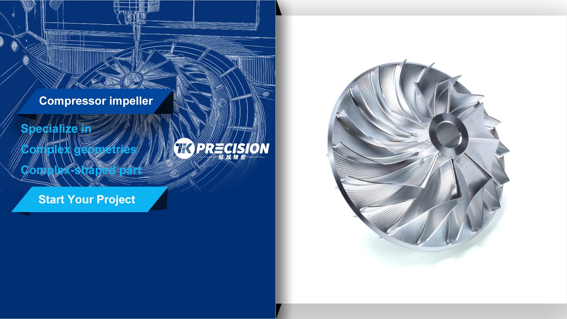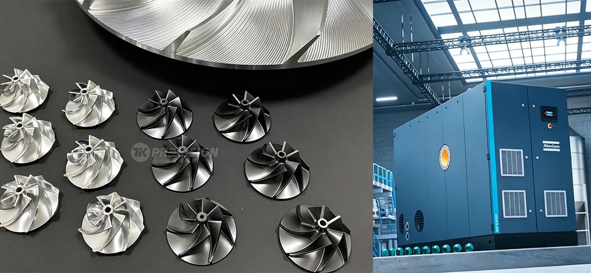
The impeller is the heart of every compressor. Whether it spins inside an oil-free magnetic-bearing centrifugal compressor, a turbocharger, a refrigerant compressor, or an air compressor package, the impeller determines how much pressure the machine builds, how efficiently it runs, and how long it lasts. Getting that geometry right requires precision CNC machining of compressor impellers to tolerances most shops cannot hold.
This guide explains how impellers are machined from customer CAD drawings, what tolerances are realistic, why a free DFM review matters, and how full-process Zeiss CMM inspection protects your design through every stage of production.
Why Compressor Impellers Demand Extreme Precision
A modern impeller can spin at tens of thousands of RPM. At those speeds, even a 0.01 mm deviation in blade profile changes airflow, pressure ratio, and efficiency. Worse, an out-of-balance or poorly profiled impeller creates vibration that shortens bearing life — a critical concern for oil-free and magnetic-bearing compressors where the rotating assembly must stay stable at high speed.
The features that make impellers difficult to machine include:
- Freeform 3D blade surfaces that twist continuously from hub to shroud
- Thin blade sections at leading and trailing edges that deflect under cutting force
- Tight profile tolerances, often in the ±0.01 to ±0.02 mm range for critical airfoil zones
- Stringent surface finish requirements to minimize aerodynamic friction
- Demanding balance requirements that depend on accurate material removal and consistent density
This is why precision impeller machining is a specialist capability rather than standard CNC work.
How CNC Machining Produces a Compressor Impeller
Precision impeller manufacturing typically combines several processes. For a closed impeller machined from solid, the typical route is:
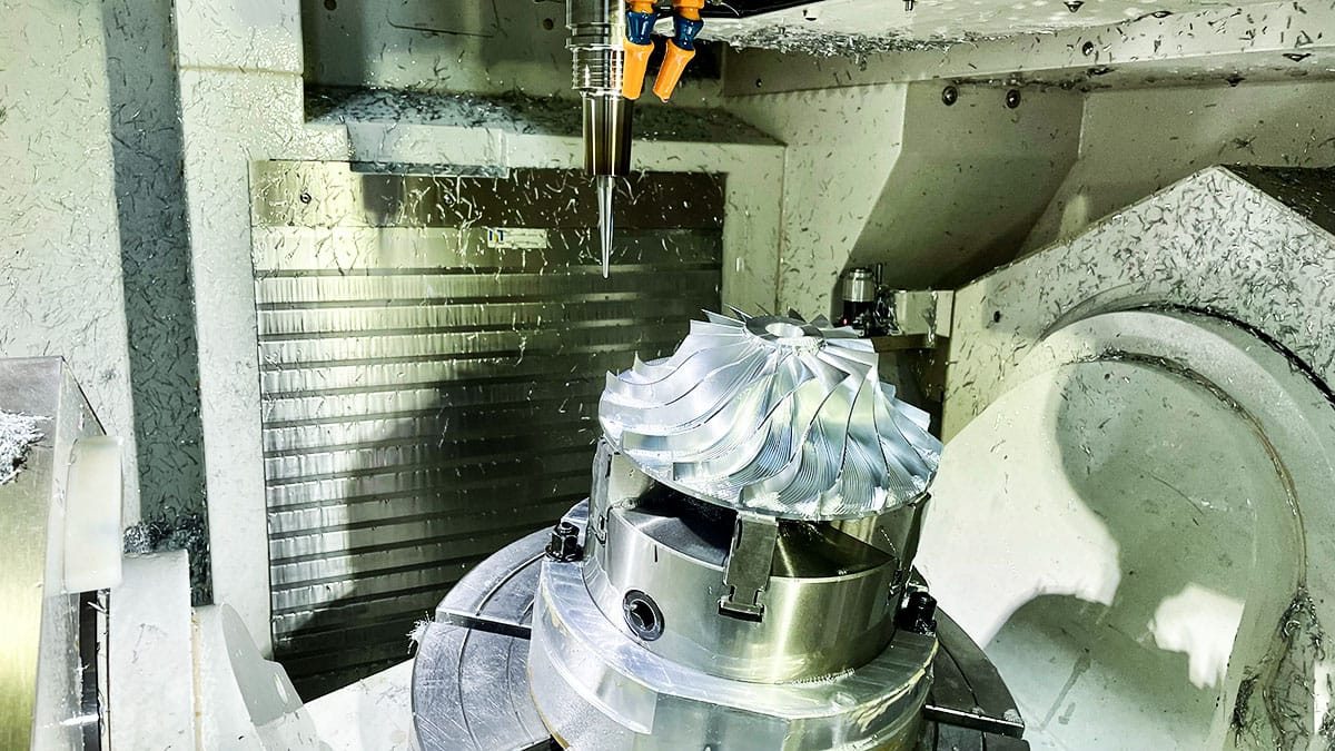
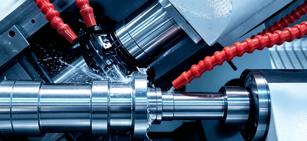
- 5-axis CNC milling — the dominant process for impeller machining. Simultaneous 5-axis toolpaths keep the cutter tangent to the twisted blade surface, avoiding gouging and delivering smooth profiles.
- Roughing to near-net shape — removes the bulk of material quickly while leaving stock for finishing and controlling heat input.
- Semi-finishing and finishing passes — progressively refine the blade surface to final profile tolerance and finish.
- Hub, bore, and backface machining — turning and boring operations establish the locating bore, seal diameters, and mating faces that reference the whole part.
- EDM (electrical discharge machining) — used for narrow channels, slots, and features that a milling cutter cannot reach.
- Manual or automated polishing — blends tool marks and sharpens leading/trailing edge radii where airflow matters most.
For impellers produced by 3D-printed or investment-cast near-net preforms, the finishing philosophy is the same: machine critical airfoil zones, bores, and faces while keeping the whole part in tolerance.
Materials Machined for Compressor Impellers
Impeller material choice depends on operating temperature, medium, and corrosion resistance. Our CNC impeller machining service regularly handles:
| Material | Typical application | Machinability note |
|---|---|---|
| Aluminum alloys (6061, 7075, 2xxx) | Air compressors, turbochargers, test rigs | Fast removal, but thin blades can deflect |
| Stainless steel (304, 316, 17-4PH) | Steam, water, and corrosive media | Work-hardens; needs rigid tooling and sharp edges |
| Titanium alloys (TC4 / Ti-6Al-4V) | High-speed and aerospace-grade compressors | Low thermal conductivity; requires controlled speeds/feeds |
| Nickel-based alloys (Inconel 718, etc.) | High-temperature compressors | Very difficult to cut; demands robust 5-axis setups |
| Alloy steel (4140, 4340) | Shaft-integrated and high-strength impellers | Balanced machinability and strength |
Tolerance Capability: What ±0.002 mm Really Means on an Impeller
Many customers ask whether 0.002 mm (2 microns) is achievable. The honest answer is: it depends on the feature and the part size.
- Holding ±0.002 mm on a bore diameter, seal seat, or balance diameter is achievable with precision grinding and temperature-controlled machining.
- Holding ±0.002 mm on a large, thin, freeform blade profile is not realistic in production because the part moves with temperature, clamping, and cutting forces.
- Realistic airfoil profile tolerances are typically ±0.01 to ±0.02 mm for production impellers, with tighter control reserved for critical zones like leading and trailing edges.
A professional impeller machining quote should tell you exactly where tight tolerances can be held and where they cannot. That is precisely what a free DFM review is for.
Free DFM Review: Catch Problems Before Machining Starts
Design for Manufacturability (DFM) review is included free with every impeller machining project. Our engineers check your CAD drawing for:
- Blade thickness vs. depth ratio and tool reachability
- Minimum fillet radii in internal channels
- Fixturing strategy for thin-wall sections
- Realistic tolerance stack-ups on critical fits
- Balance and inspection strategy feasibility
The result is a clear report: what machines cleanly, what needs adjustment, and what will cost extra — before you spend a single dollar on tooling.
Upload Your CAD Drawing and Get a Quote
Getting started is simple:
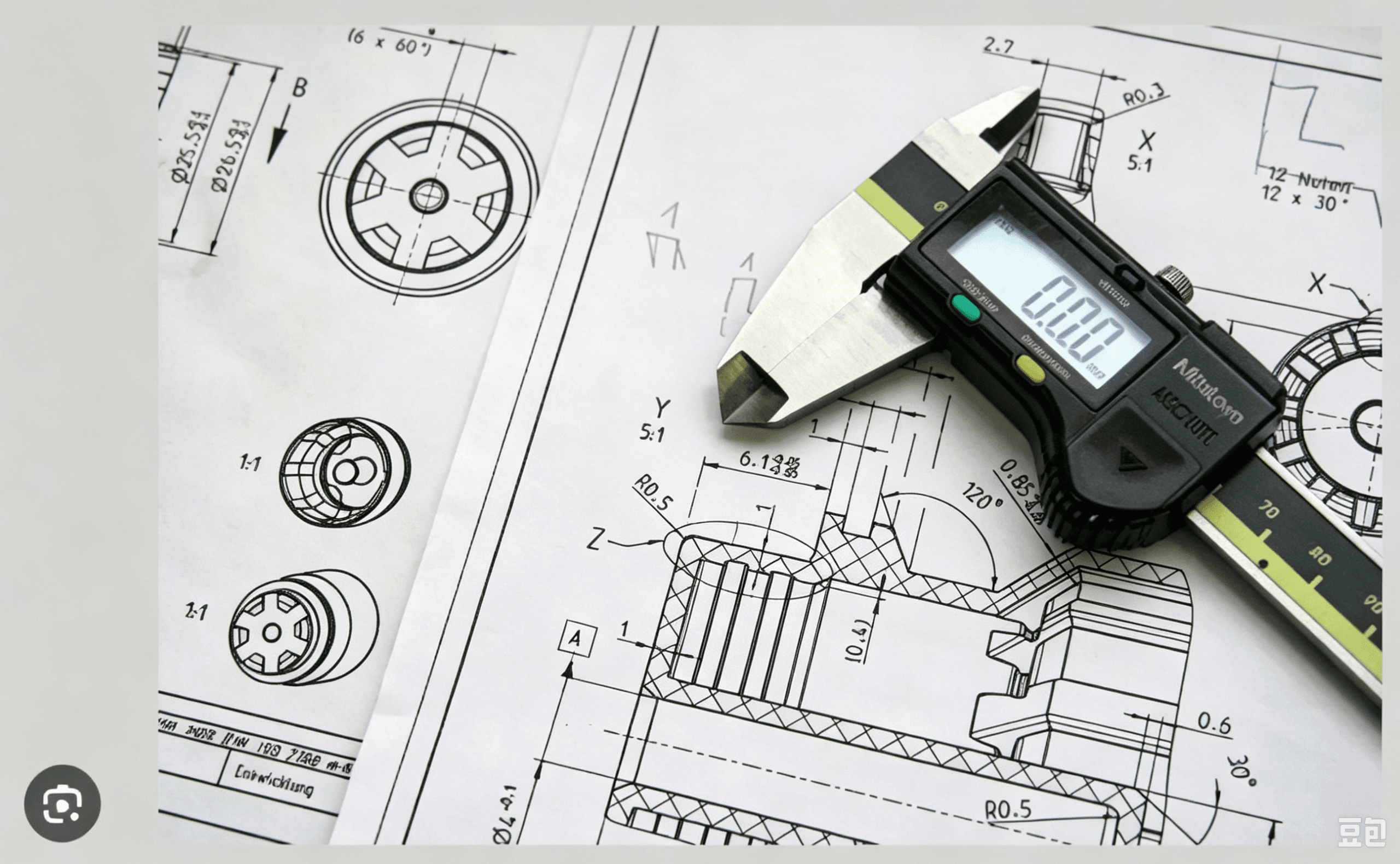
- Upload your CAD file — STEP (.stp/.step), IGES, SolidWorks, or 2D PDF/DFT drawings are all accepted.
- Include your requirements — material, quantity, critical tolerances, surface finish, and any coating or balance class.
- Receive free DFM feedback and a quote — normally within one business day.
- Approve, then release to production — toolpaths, fixtures, and inspection plans are built around your approved revision.
Because every impeller is machined to print, you keep full control of your design. We do not sell parts “off the shelf” — we manufacture exactly what you upload.
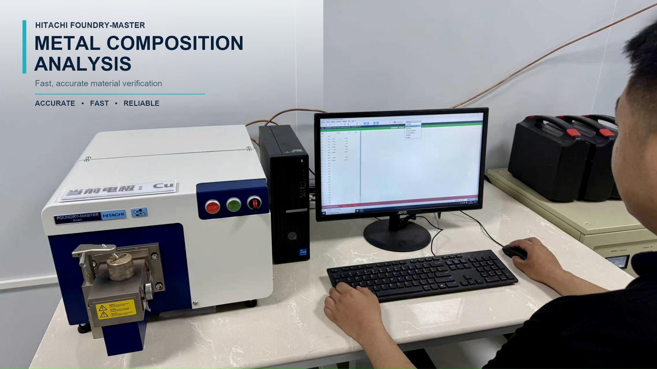
Full-Process Zeiss CMM Inspection
Dimensional accuracy is meaningless if it is not measured. Every impeller project includes:
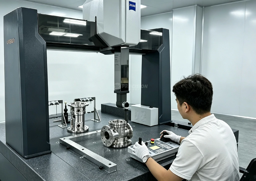
- Zeiss CMM inspection of bores, faces, blade profiles, and critical dimensions
- Airfoil profile scanning against your CAD model for deviation maps
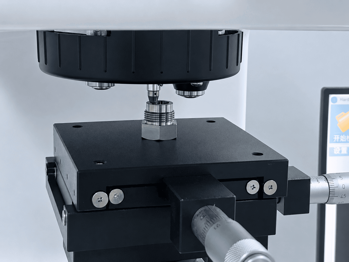
- Surface roughness measurement on finished surfaces
- Dynamic balancing where the application requires it
- Full inspection reports with dimensional data, drawings, and material certificates
You receive documented proof that the part meets your drawing, not just a promise.
From Prototype to Production
Impeller development rarely stops at one part. We support:
- Single prototypes for rig testing and validation
- Small batches for pilot builds
- Repeat production runs with controlled processes and archived programs
Since toolpaths, fixtures, and inspection programs are saved, repeat orders are faster, more consistent, and easier to quote.
FAQ
What is the best CAD format for an impeller quote?
STEP (.step/.stp) is preferred because it preserves solid geometry reliably across software platforms. IGES and native SolidWorks files are also accepted, along with a 2D drawing showing tolerances.
Can you machine an impeller from a scanned model?
Yes. If you provide a mesh or point cloud, our engineers can rebuild a machinable solid model and confirm critical dimensions with you before production.
How tight a tolerance can you hold on impeller bores?
Precision-ground bores and seal diameters can be held to ±0.002 mm (2 microns) under controlled conditions. Freeform blade profiles are realistically held to ±0.01 to ±0.02 mm.
Do you balance impellers?
Yes, where required. Balancing is performed to the specified balance quality grade (such as G2.5 or better) using precision balancing equipment, and reports are supplied with the parts.
Is DFM review really free?
Yes. The DFM review is included at no cost in every quotation. It protects you from expensive surprises and helps us quote accurately the first time.
Upload your CAD drawing for a free DFM review and precision impeller machining quote — our engineers will confirm tolerances, materials, and lead time before you commit to production.