

Author note: This is my working note walking through AMT Lynx public specs. Not an official design report, just a back‑of‑the‑book energy balance check. I’m not guessing blade geometry or unpublished test data.
Blog for tikprecision.com | Aerospace Turbomachinery Notes

Most people new to small turbojets get the turbine job wrong at first glance. They picture it like a power‑station turbine, built to spin something and output usable shaft power. That’s not what this one does.
On AMT’s classic layout — single centrifugal compressor plus one single‑stage axial turbine — the turbine’s primary job is to drive the compressor. Thrust comes from the nozzle, not from shaft output. The single‑stage layout keeps the core compact, but that puts a hard constraint on the stage: it has to extract enough work from hot gas to keep the rotor on speed, while leaving the gas in a usable state for the nozzle downstream.
This balance is easy to miss. Extract too little enthalpy, and the compressor can’t maintain the design speed. Pull too much, and you rob the nozzle of total pressure and temperature you need for thrust. There is no free, independent power budget you can allocate arbitrarily. The compressor demand and nozzle expansion are locked together. That’s why you can’t take these numbers and treat it like a generator gas turbine.
AMT has refined this architecture across multiple thrust variants. That doesn’t mean it eliminates all trade‑offs. It means they landed on a set of compromises that are buildable, testable and stable within their target envelope. That’s what I want to unpack here.

First, get the mass flow rightI’m using AMT Lynx published figures: air flow 2.500 kg/s, fuel burn 3600 g/min. Convert fuel: 0.060 kg/s.
Important detail: the gas that hits the turbine includes fuel mass. If you run the enthalpy drop only on inlet air flow, you get a consistent, quiet bias in your temperature numbers. It’s not huge, but it adds up when you stack sensitivity cases.
Real engines have bleed air, cooling paths, lubrication streams. Some bleed air gets routed back upstream of the turbine and rejoins the main flow; it’s not a permanent loss. The problem is, we don’t have the internal flow schematic from AMT. So I’m stating the assumptions clearly instead of inventing a cooling split.
Mass flow definition controls everything. The same turbine power will give a different ΔT depending on whether you use air‑only or fuel‑included gas flow. Any temperature drop number is meaningless unless you write down which flow basis you used.
Calculating the required turbine temperature drop

I reuse the compressor setup from earlier notes: inlet total temperature 288.15 K, pressure ratio 4, assumed compressor efficiency 0.75, air (c_p=1.005\ \text{kJ/(kg·K)}). Specific compression work lands around 187.65 kJ/kg. For 2.5 kg/s air flow, compressor shaft demand is ~469.13 kW.
This is an assumed efficiency, not measured AMT component data.
I add mechanical efficiency 0.98 between turbine gas power and compressor shaft load, gas (c_p=1.15\ \text{kJ/(kg·K)}), no extra accessory draw for this simple case. Solving the steady balance gives a mean total temperature drop across the turbine of roughly 162.6 K.
Again, this is a conditional estimate. Constant specific heat is a shortcut for hand checks. Real gas properties shift with temperature and mixture; serious hot‑section work uses enthalpy tables, not fixed (c_p\Delta T). This is good for sizing and sensitivity sweeps, not for material life calculations.
I ran three compressor efficiency points to show the coupling:
| Compressor efficiency | Compressor power | Turbine ΔT |
|---|---|---|
| 0.70 | 502.64 kW | 174.22 K |
| 0.75 | 469.13 kW | 162.60 K |
| 0.80 | 439.81 kW | 152.44 K |
Higher compressor efficiency reduces the shaft load. The turbine does less work, without touching the turbine geometry.

But don’t jump to the easy conclusion: saved power = extra thrust. The ECU will rebalance fuel flow, speed and thermal state. The 10.16 K drop in required turbine ΔT from baseline to 0.80 efficiency does not automatically translate to a 10.16 K rise in exhaust temperature. Only under fixed turbine inlet conditions does that mapping hold. Local efficiency gains do not directly convert to thrust. The whole cycle has to re‑match.
Exhaust temperature is not turbine inlet temperatureLynx datasheet lists normal exhaust temperature at 800 ℃, 1073.15 K. This measurement is downstream of the turbine, not combustor exit / turbine inlet. I see this mix‑up constantly in hobby jet discussions.
If we take that exhaust value as turbine outlet total temperature and add the 162.6 K calculated drop, we back‑calculate an inlet total temperature near 1235.75 K.
That “if” is doing a lot of work.
Thermocouple readings are noisy. They are affected by circumferential hot streaks, radiation error, recovery factor, probe location and response time. A couple of point measurements do not equal mass‑weighted average total temperature. Our compressor efficiency, mechanical loss and gas property values are all assumptions. This back‑calc is a consistency check, not a way to read the secret design point off the datasheet.
Also, separate nominal operating temperature from hardware protection limits. Different AMT document revisions list different max EGT values. I don’t pick the highest one and treat it as the target run point.
The best use for this reverse calculation is to flag what measurements we are missing. If you wanted to tighten the uncertainty, you’d add properly instrumented total pressure and temperature planes, lock down the flow measurement definition, and get component efficiency data. Adding more decimal places to the calculation does not fix the missing test data.
Turbine efficiency changes what the nozzle seesFor a fixed work extraction and fixed inlet state, lower turbine efficiency means a larger pressure drop across the stage. The turbine can still supply the kilowatts the compressor needs, but the residual total pressure feeding the nozzle will be lower.
That is why power balance alone is incomplete. You have to track enthalpy and pressure together.
Combustor pressure loss and turbine expansion both reduce the gas pressure before the nozzle. The published compressor pressure ratio of 4 is not the nozzle expansion ratio. With limited public data, the responsible approach is to map a range of possible operating states, not solve for one “true” turbine map. Multiple assumption sets can reproduce rated thrust, which means the model is under‑constrained until independent pressure measurements exist.
You cannot keep stacking single‑stage loadingA single stage is attractive for low part count and short axial length. But there is a ceiling on how much work you can pack into one row.
Higher stage loading increases flow turning, secondary flow and separation risk. Exit swirl matters too. Tangential velocity does not convert cleanly to axial thrust in the nozzle. Turbine exit flow angle is not just an aerodynamic footnote; it couples directly to nozzle performance.
Structurally, higher inlet temperature and higher rotational speed ramp up centrifugal stress and thermal load. Blade material, coating, creep and thermal deformation set hard boundaries. We don’t have the material and life data from AMT, so I won’t casually suggest turning up speed or temperature.
One often overlooked point: single‑stage designs still need tight control of hot running clearance. Cold static gap is not representative. Rotor and casing heat up and expand at different rates during transients. The worst‑case clearance condition sets the safety margin.
Clearance is a classic trade‑off. Too much gap, leakage loss eats efficiency. Too little, rubbing risk. Surface finish is also more nuanced than “polish it smooth”. Erosion, deposition and subsurface machining damage change heat transfer and fatigue behaviour. A turbojet can still hit its rated thrust while hiding rising internal losses; the controller just burns more fuel to compensate. Thrust, fuel flow, EGT and vibration need to be read together.
What counts as a verifiable improvement?I try to frame changes only where there is a clear test path. No hand‑wavy “this will improve efficiency” claims.
- Cut compressor power draw, but test at matched thrust. Monitor turbine outlet total pressure and fuel consumption. Changing an efficiency knob in the spreadsheet is not proof it works.
- Stabilise hot‑state clearance consistency. Look at warm‑up transients, repeated assembly and thermal cycles. The goal is lower scatter, not chasing the smallest nominal gap.
- Tune combustor exit profiles to reduce hot spots. Every change has a trade: a cooler metal surface may come with higher combustor pressure loss. You have to audit the full affected zone, not just report the best thermocouple.
- Add better instrumentation planes. Independent pressure and temperature measurements reduce the ambiguity in inverse calculations. This might not add Newtons on the day, but it makes the next design cycle much less guesswork.
When comparing two turbine designs, compare them at the same mission condition. Same thrust demand, same inlet environment, same duty cycle. A turbine with a shiny peak efficiency at some off‑design point is not automatically better if it runs thirsty or hot at the operating point you actually use.
Good test discipline means variable isolation. If you swap a turbine and also have fouled compressor blades or moved thermocouples, you cannot reliably attribute the result. Alternating test runs, consistent teardown checks and uncertainty budgets are non‑negotiable. A few percent gain means nothing if test repeatability is wider than that.
Mechanical loss: boundaries matterIn this model, mechanical efficiency lumps bearing drag and accessory losses between turbine gas power and compressor shaft power. This is a convenient lumped parameter. The trap is double‑counting. If you later pull out bearing power as a separate term, you must adjust the mechanical efficiency term. More equations do not automatically mean more accurate.
Sensitivity check: mechanical efficiency from 0.98 to 0.96 pushes required turbine ΔT from 162.60 K to 165.99 K. The shift is smaller than compressor efficiency effects, but local heat in bearings and seals still matters for reliability. Friction heat does not all dump into the main gas stream; it leaves through oil, conduction and cooling air. If your question is bearing temperature, you need a thermal network, not a bulk cycle model.

When measurements are unavailable, publish sensitivity bands. Do not only publish one fixed answer. Readers need to see which assumptions dominate the result, so they know which test data to prioritise.
Closing
For engines like the AMT Lynx, the single‑stage axial turbine’s job is multi‑dimensional: deliver compressor drive power in a compact package, hold thermal load within material limits, preserve enough pressure energy for the nozzle, and keep clearance and repeatability manufacturable.
The numbers here are a sanity check on the energy scale, not validated component data. CFD, rig test and blade maps are required before you touch hardware. Good turbine design is a sequence of deliberate compromises: aerodynamic performance, structural life, tip clearance, coatings and machining repeatability all weigh against each other.

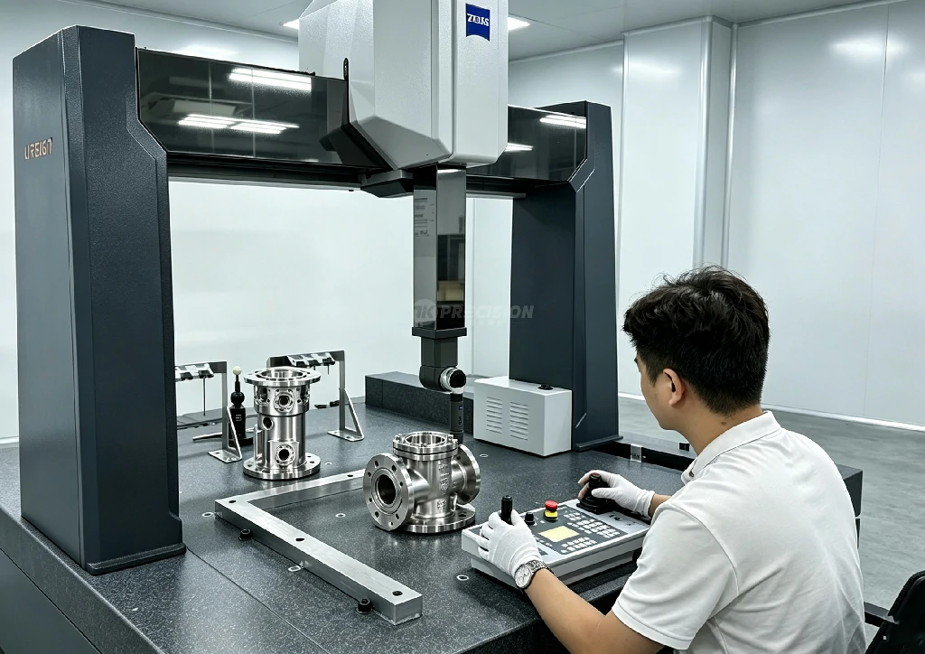
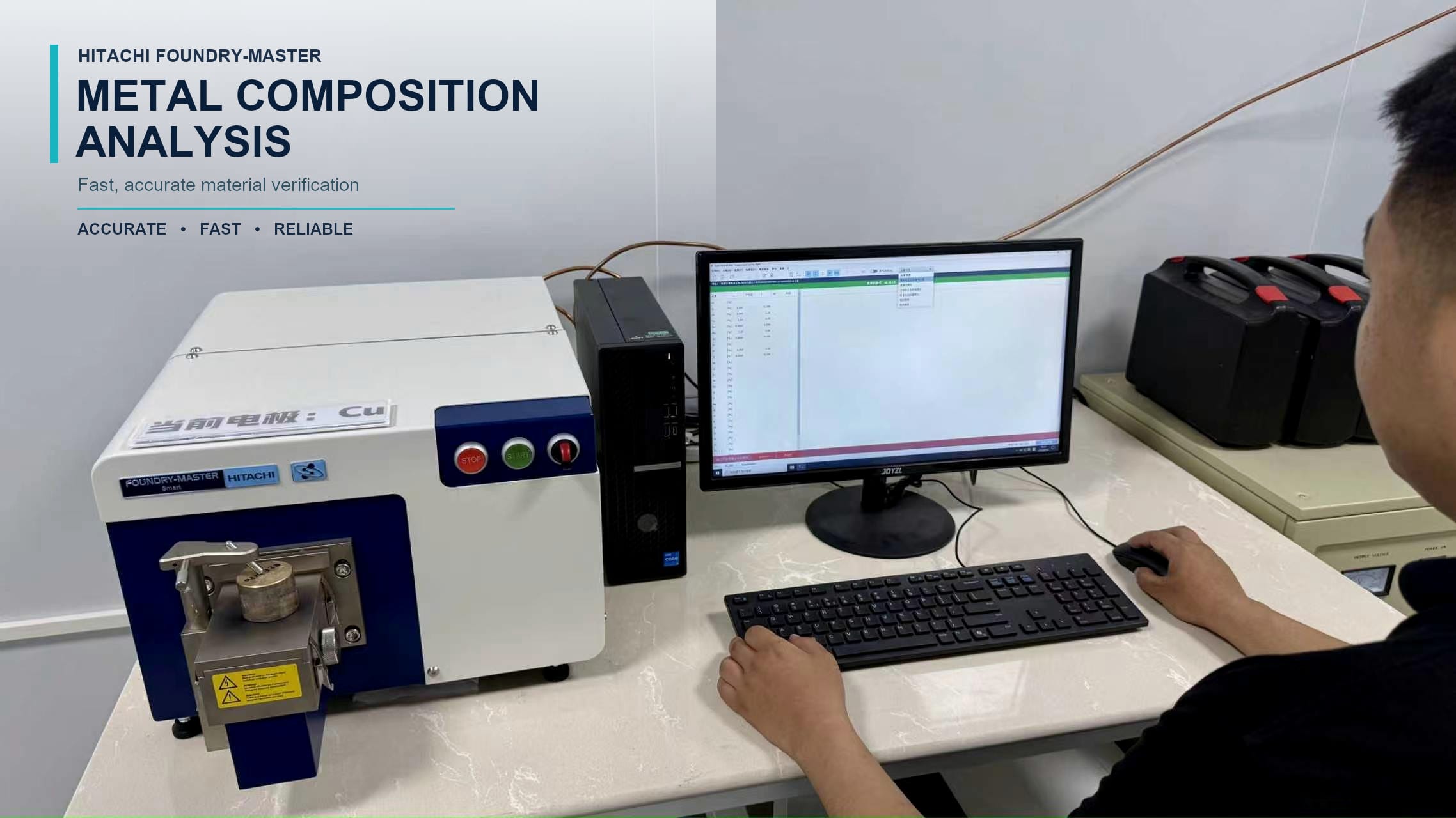
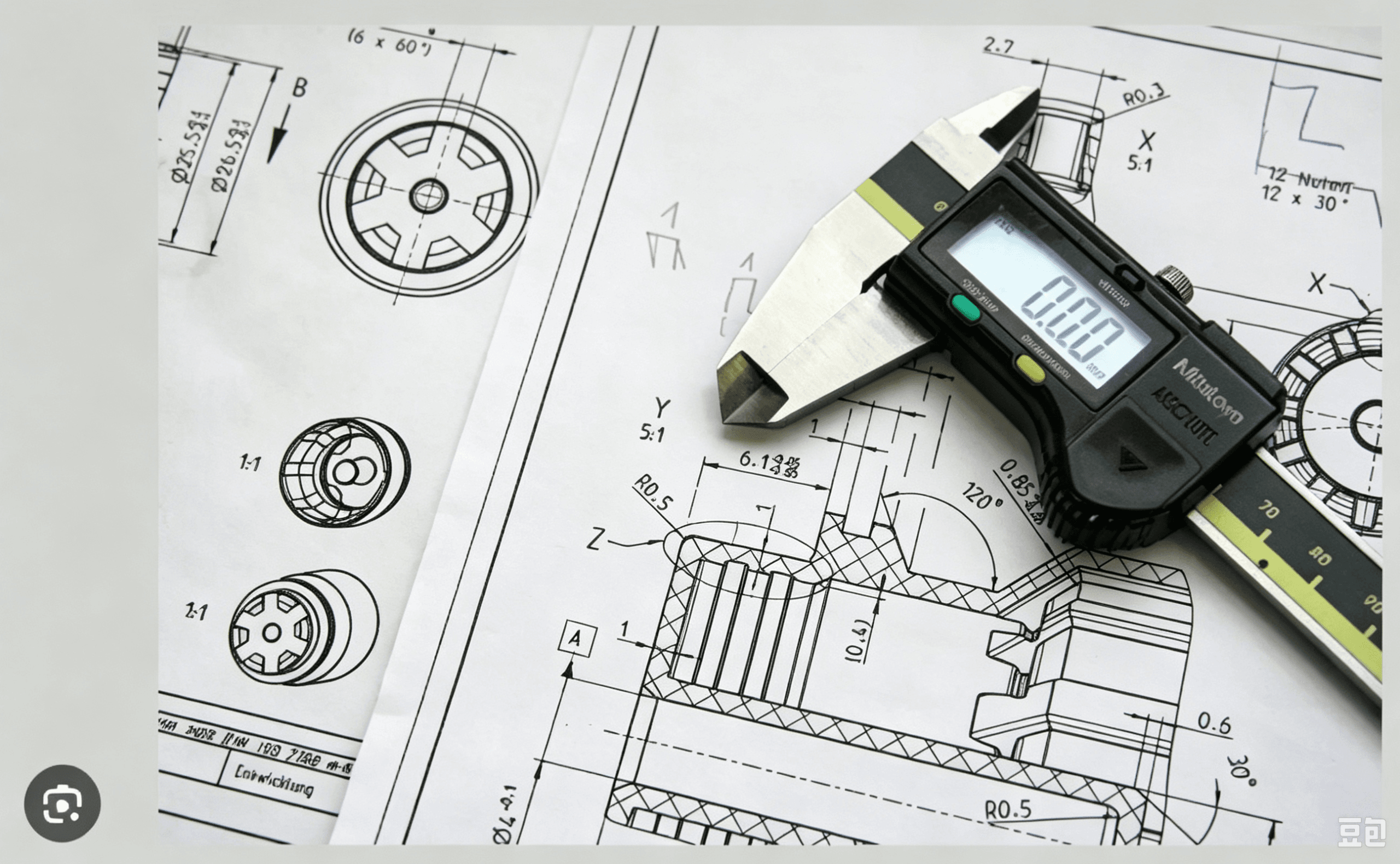
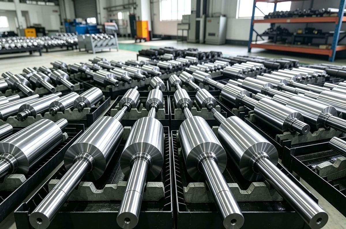
At Tik Precision, we support prototype and low‑volume turbomachinery parts for these kinds of small gas turbine cores. We machine turbine blades, wheel hubs, compressor impellers and hot‑section fixtures in Inconel, titanium and high‑strength stainless using 5‑axis CNC. Every aerospace drawing goes through a DFM review up front. We check for manufacturability, tolerance stack, tool access and surface integrity before quoting.
If you are developing turbojet turbine or compressor hardware, send your STEP/IGS files and 2D tolerance drawings for a free DFM review and quotation.