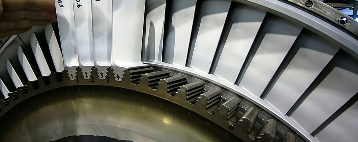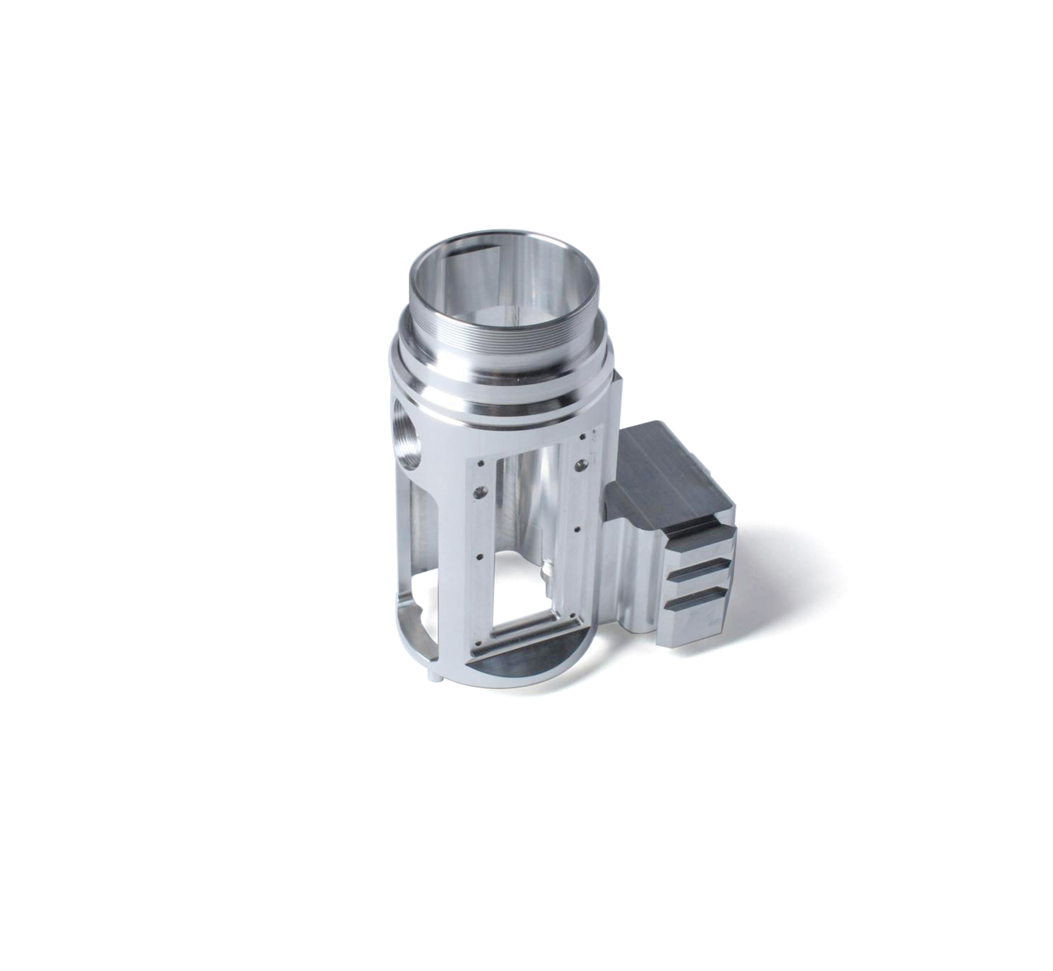
The duct — also called the shroud, housing, or nacelle — is the defining feature that distinguishes a ducted fan from an open propeller. Far from being a simple cylindrical tube, the duct is a carefully shaped aerodynamic surface whose internal and external profiles determine fan efficiency, thrust, and noise characteristics. CNC machining of ducted fan housings presents its own set of challenges: large diameters with tight tolerances, thin wall sections, deep internal bores, and the need to maintain concentricity between the rotor axis and the duct bore. This article covers the machining strategies and quality requirements for precision ducted fan housings.
Duct Aerodynamic Design: Why Shape Matters
A well-designed duct performs three aerodynamic functions:
- Inlet flow conditioning: The inlet lip accelerates and smoothly turns the incoming flow into the fan plane. A properly shaped inlet lip prevents flow separation at high angles of attack (important for UAVs in forward flight or hover in crosswinds). The lip radius and profile are critical — too sharp and flow separates; too blunt and external drag increases.
- Tip vortex suppression: The cylindrical portion of the duct blocks the formation of blade tip vortices, eliminating induced drag at the blade tip and allowing the fan to operate at higher blade loading.
- Diffuser pressure recovery: Downstream of the fan, a diverging duct section (diffuser) decelerates the high-velocity flow, converting dynamic pressure into static pressure. This pressure recovery increases the overall system efficiency. The diffuser”s divergence angle is limited to approximately 7-10° (included angle) to prevent flow separation.
Duct Geometry and Tolerancing
Critical Features
| Feature | Function | Typical Tolerance |
|---|---|---|
| Bore ID at rotor plane | Establishes the tip clearance gap with the fan blades | Diameter ±0.03 mm; roundness 0.02 mm |
| Inlet lip radius profile | Controls flow acceleration into the fan | Profile ±0.1 mm; surface finish Ra 0.8 µm |
| Diffuser section profile | Pressure recovery downstream of fan | Profile ±0.1 mm; divergence angle tolerance ±0.5° |
| Duct bore concentricity to bearing bore | Ensures uniform tip clearance around circumference | 0.03 mm TIR (Total Indicator Reading) |
| Mounting flange faces | Attachment to vehicle structure or other components | Flatness 0.05 mm; perpendicularity 0.03 mm to bore axis |
| Motor mount / strut attachment points | Support the motor and center it within the duct | Position ±0.05 mm relative to duct axis |
| Stator vane slots or attachment features | Mounting of downstream guide vanes | Angular position ±0.25°; radial position ±0.05 mm |
CNC Machining Strategies for Ducted Fan Housings
Machining Approach by Duct Configuration
One-piece ducts (small to medium diameter, < 300 mm):
- Turn the OD profile (inlet lip exterior, cylindrical section, diffuser exterior) on a CNC lathe. The external profile is typically conical or contoured for external aerodynamic performance.
- Bore the ID on the same lathe in the same setup: rough-bore the inlet, cylindrical section, and diffuser ID. Semi-finish and finish bore with tight tolerance control.
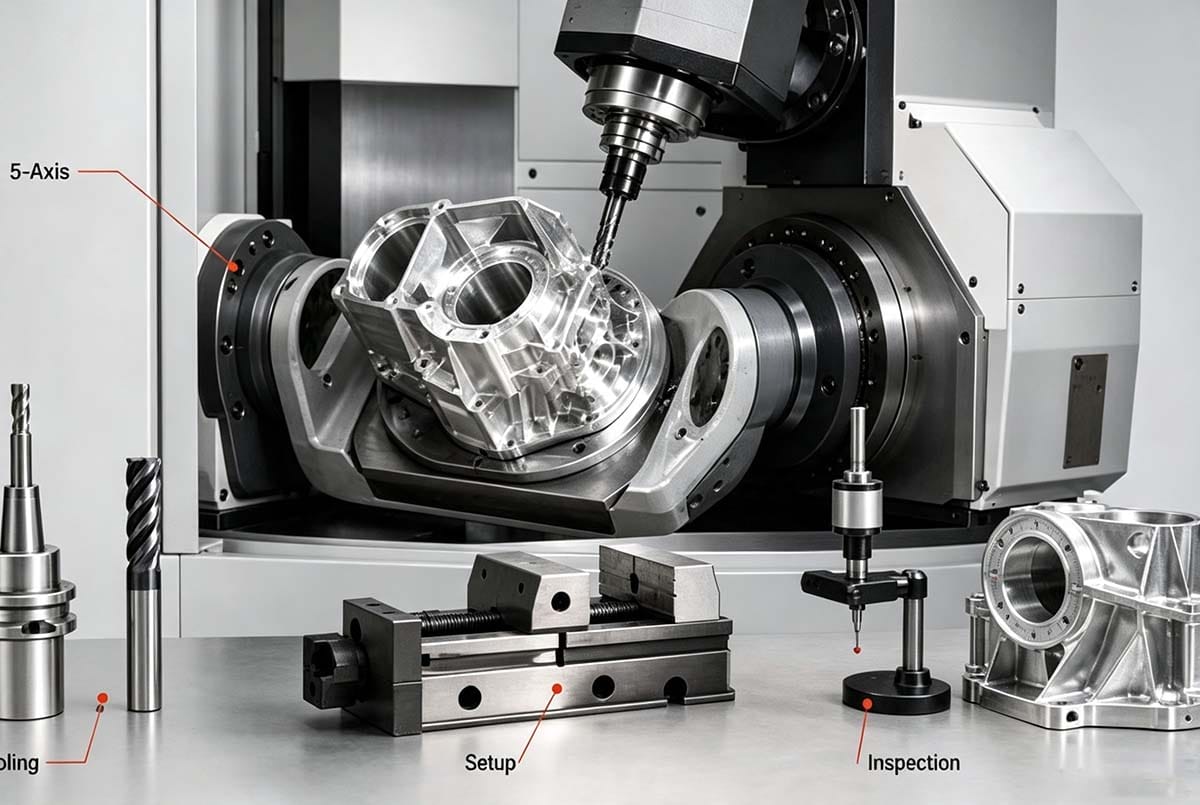
- Transfer to 5-axis mill for: strut attachment features, stator vane mounting slots, flange bolt patterns, accessory mounting pads, and any non-axisymmetric features.
- Advantage: One turning setup establishes concentricity between the OD, ID, and bearing bore — the fundamental relationship for uniform tip clearance.
Split ducts (medium to large diameter, > 300 mm, or for assembly access):
- Split ducts are machined in two halves that bolt together along a horizontal or vertical parting plane.
- Each half is machined on a 5-axis mill: the internal bore surface is machined as a semi-cylindrical pocket; the flange faces at the parting plane are machined flat and square.
- After assembly, the assembled duct may be honed or finish-bored as a unit to achieve the final ID tolerance and roundness. The bolt pattern must provide sufficient clamping force to maintain bore roundness under operating pressure differentials.
- Dowel pins or precision ground rabbets at the parting plane ensure repeatable alignment when the halves are separated and reassembled.
Thin-wall ducts (lightweight UAV applications):
- Wall thickness as low as 0.8-1.5 mm. Machined from aluminum tube or from a solid billet.
- Turning thin-wall sections requires careful management of clamping forces — standard 3-jaw or 4-jaw chucks can distort the thin wall into a triangular or square shape that springs back after unclamping, leaving the bore out of round.
- Solutions: Use pie-jaw chucks (segmented jaws that distribute clamping force around a larger arc), pot chucks (collet-style fixturing for the OD), or vacuum fixturing. Machine the ID in a stress-relieved state, and take light finish cuts (0.1-0.2 mm DOC) to minimize cutting forces that could deflect the thin wall.
Specialized Machining Operations
Internal Grooves and Abradable Coatings
Some ducted fan designs incorporate an abradable coating or a groove in the duct ID at the rotor plane. If the blade tips contact the duct under transient conditions (maneuver loads, thermal expansion, casing ovalization from mounting loads), the tips abrade the coating rather than suffering damage. The groove or coating pocket is machined into the duct ID during the boring operation. Depth tolerance of ±0.025 mm ensures consistent coating thickness and hence consistent tip clearance.
Acoustic Treatment Features
For noise-sensitive applications (urban UAVs, indoor ducted fans), the duct ID downstream of the fan may incorporate acoustic treatment — a perforated inner skin backed by a cavity (Helmholtz resonator) that absorbs acoustic energy at the blade-passing frequency. Machining these features involves:
- Drilling or micro-milling arrays of small holes (0.5-2.0 mm diameter) in the duct wall
- Machining the backing cavity as a circumferential ring pocket on the duct OD
- Ensuring that the perforations do not create burrs on the ID that would disrupt the boundary layer
Inlet Lip Machining
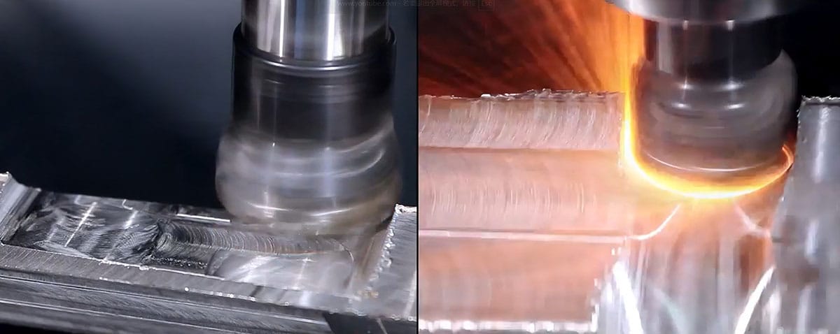
The inlet lip is the most aerodynamically sensitive feature of the duct. The lip profile typically follows an elliptical or NACA inlet shape, with the radius of curvature decreasing from the highlight (the forwardmost point) to the throat. Machining requires smooth continuity of the surface — no visible steps between passes, no dwell marks from tool hesitation. 5-axis contour milling with a ball end mill and fine stepover (0.05-0.1 mm) is standard. The toolpath should be a continuous spiral rather than discrete Z-levels to avoid witness marks.
Inspection and Verification
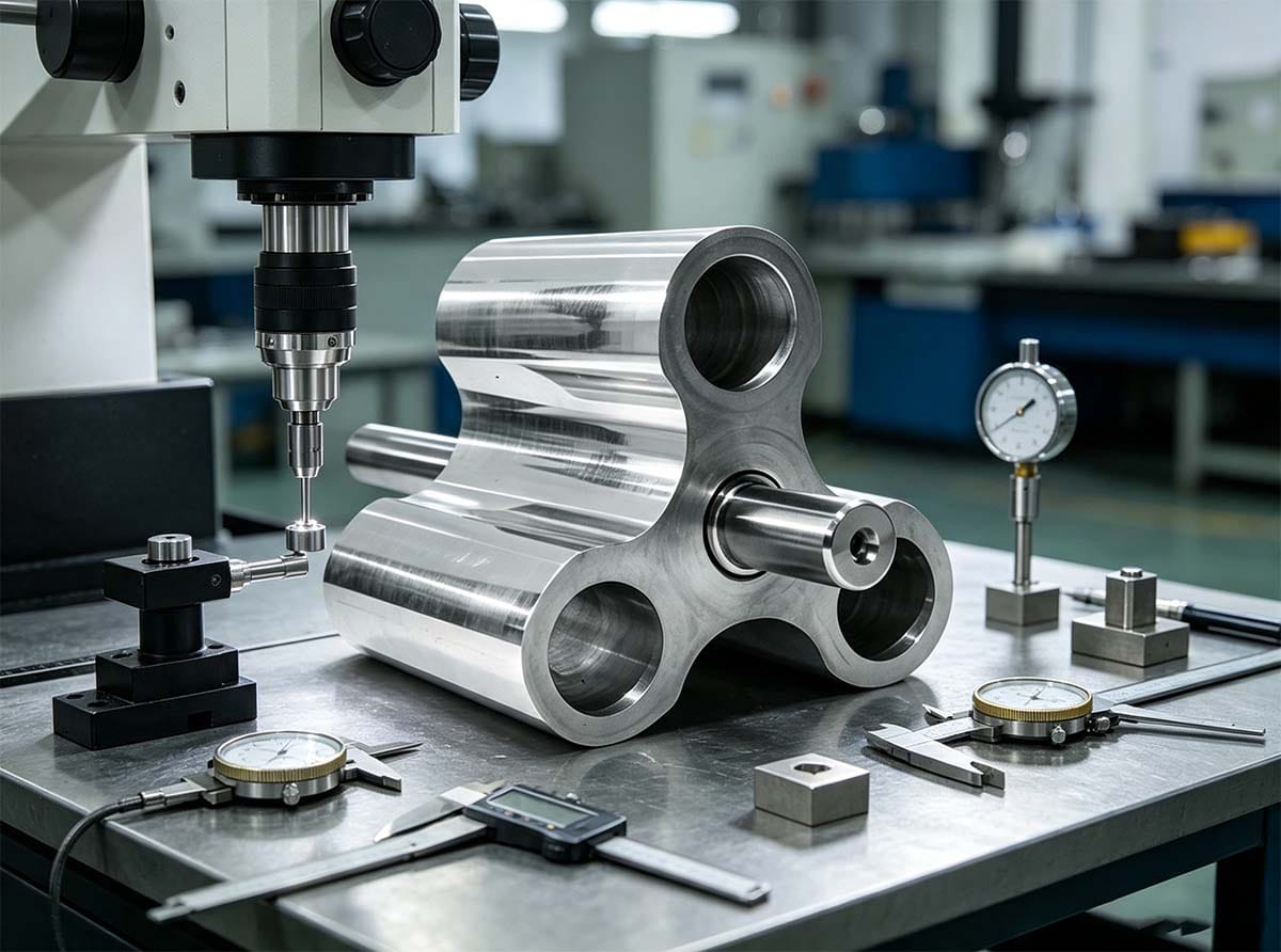
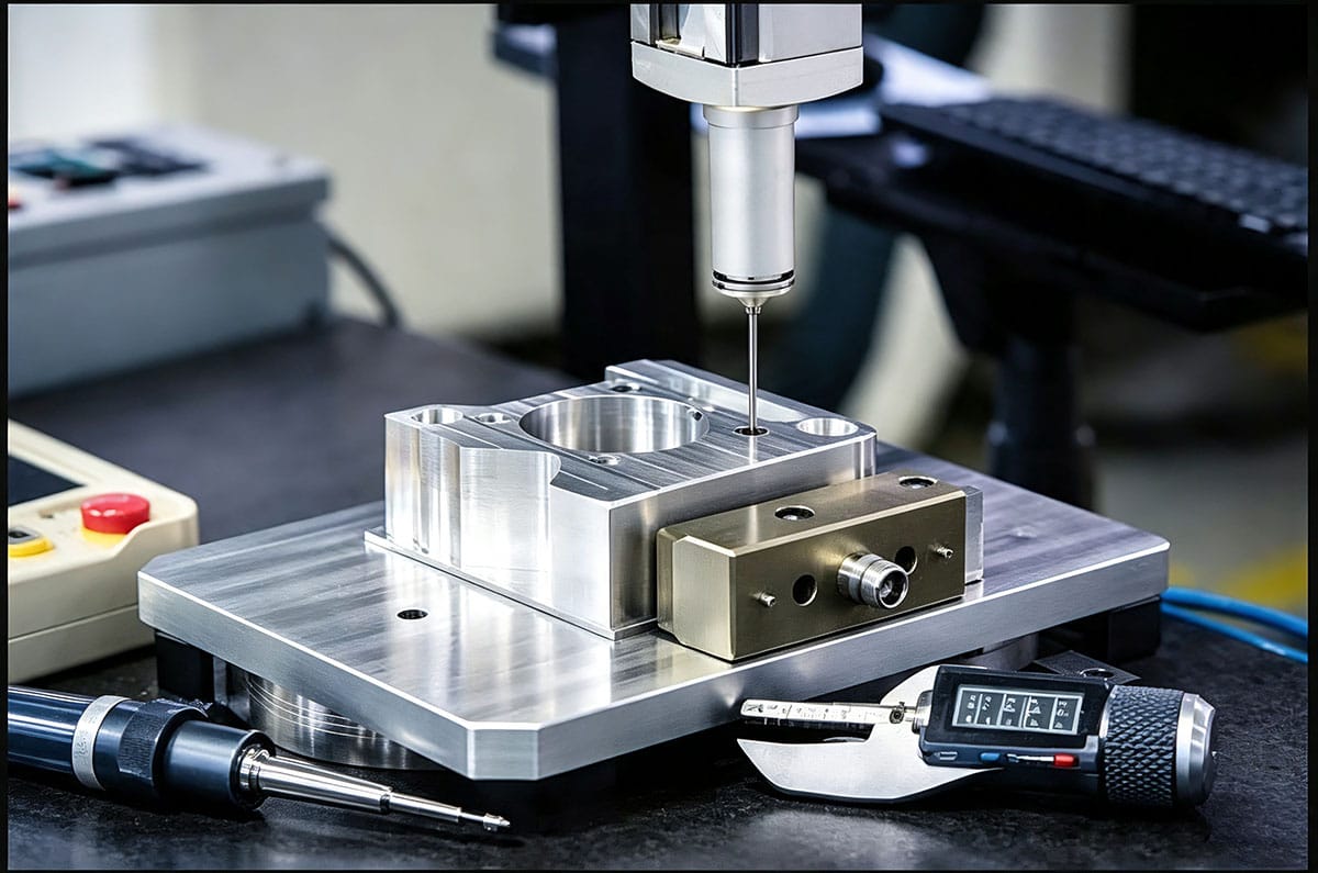
- Bore diameter and roundness: Measured with a CMM (multiple diameters probed and least-squares circle fitted), a bore gauge (diameter only), or an air gauge (non-contact, high-resolution diameter measurement). Roundness should be measured at multiple axial positions — at a minimum, at the rotor plane and at both bearing locations.
- Concentricity stack-up: The duct bore must be concentric with the bearing bores (which establish the rotor axis). This can be verified by mounting the duct on a CMM rotary table, measuring the bore and bearing features in the same coordinate system, and calculating the concentricity error.
- Surface finish: Ra 0.8 µm on the duct ID is typical. Rougher surfaces increase wall friction, reducing fan efficiency. However, excessively smooth surfaces (Ra < 0.1 µm) provide no additional aerodynamic benefit and increase manufacturing cost.
Tik Precision machines ducted fan housings in aluminum and titanium on our CNC turning and 5-axis milling platforms. From small UAV ducts to industrial-scale blower housings, we provide the dimensional accuracy and surface quality that ducted fan performance demands. Contact us to discuss your duct or housing requirements.



.jpg)